How a retaining wall is regulated in Missouri depends on three layers of authority: the building code adopted by the local jurisdiction, the height and loading thresholds written into that code, and the state law that defines what constitutes professional engineering. A PE stamp on retaining wall plans is a licensed Professional Engineer’s sealed certification that the wall’s structural design meets the applicable building code requirements for overturning resistance, sliding resistance, bearing capacity, and drainage, based on site-specific soil and loading conditions. In most Missouri jurisdictions, the International Building Code exempts retaining walls under 4 feet from permit requirements (IBC Section 105.2). St. Louis County sets a stricter threshold, triggering permits at 3 feet for residential walls. RSMo 327.181 operates above both, defining any structural design that affects public health, safety, or welfare as professional engineering that requires licensure. Walls of any height that support a surcharge, meaning any load applied to the soil behind or above the wall, require engineering regardless of where they fall on the height scale.
This page explains where each threshold applies, how height is measured for code purposes, what conditions override the general exemptions, and what PE-stamped plans contain.
What Is a PE Stamp and What Does It Certify?
The legal weight of a PE stamp comes from what it represents: personal professional liability for the structural adequacy of a design. A PE stamp is the official seal of a licensed Professional Engineer affixed to structural drawings and calculations, certifying that the design meets applicable building codes, accounts for site-specific conditions, and satisfies the minimum safety factors required by the governing structural standards. In Missouri, the authority to seal engineering documents is restricted to individuals licensed under RSMo 327.181. That statute defines professional engineering as any service involving structures or processes where public health, safety, or welfare depends on the work being performed correctly.
RSMo 327.191 establishes the enforcement side. It prohibits any person from practicing or offering to practice professional engineering without a license issued by the Missouri Board for Architects, Professional Engineers, Professional Land Surveyors and Professional Landscape Architects. Violation is a Class A misdemeanor. The statute exists because structural design errors in load-bearing systems like retaining walls create consequences that extend beyond the property line.
The stamp itself follows a prescribed format under Missouri administrative rule 4 CSR 30-21. It must include the engineer’s full legal name, Missouri license number, and license expiration date. The seal diameter falls between 1-3/4 inches minimum and 2-1/4 inches maximum. When an engineer applies that stamp to a set of retaining wall plans, the stamp binds the engineer personally to the structural adequacy of the design. If the wall fails because the design was deficient, the engineer who stamped the plans carries professional and legal liability for that failure.
A PE stamp is not a procedural checkbox attached to the permitting process. It binds the engineer to a specific set of site conditions: the soil classification, the loading scenario, the drainage design, and the structural calculations that connect them. The stamp says those conditions were evaluated and the design accounts for them.
Missouri Height Thresholds for PE-Stamped Retaining Wall Plans
Whether a retaining wall triggers a PE stamp requirement in Missouri depends on which code the local jurisdiction has adopted and how strictly that jurisdiction enforces it. The state does not impose a single height threshold. Three overlapping regulatory layers set different triggers, and the most restrictive rule that applies to the project site governs.\
| Code / Authority | Height Threshold | What It Triggers | Measurement Basis | Source |
|---|---|---|---|---|
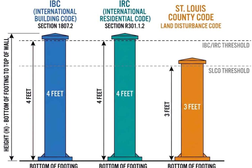
| IBC Section 105.2, Item 4 | 4 feet | Building permit required; PE-stamped plans required for structural design | Bottom of footing to top of wall | IBC 2018/2021 |
| IRC Section R105.2, Item 3 | 4 feet | Same as IBC; residential code equivalent | Bottom of footing to top of wall | IRC 2015 |
| IRC Section R404.4 | 48 inches of unbalanced fill | Engineering required for foundation walls retaining soil beyond this depth | Retained soil height (unbalanced fill), not total wall height | IRC 2015 |
| St. Louis County Residential Retaining Walls Checklist | 3 feet | Building permit required for residential walls in unincorporated SLCO and contracted municipalities | Bottom of footing to top of wall | SLCO Ordinance #27,654-Ch.1116 (2015 IRC/IBC adoption) |
| Other MO municipalities (e.g., City of St. Louis, municipalities in St. Charles County) | Varies by adopted code edition | Depends on which IBC/IRC version the municipality enforces and whether local amendments apply | Verify with local building department before design | Municipality-specific |
The IBC and IRC thresholds align at 4 feet for most wall types, but they measure different things. IBC 105.2 measures total wall height from footing to cap. IRC R404.4 measures unbalanced fill: the height of retained soil on one side minus the soil level on the other. A wall with 3 feet of exposed face on the high side and 1 foot of soil against the low side retains only 2 feet of unbalanced fill, even if total wall height exceeds 4 feet.
St. Louis County’s 3-foot threshold is the stricter standard in the metro area. A residential wall that would be permit-exempt under the IBC in a neighboring municipality requires a permit in unincorporated St. Louis County. The threshold can change across a single street where jurisdictional boundaries shift, so confirming which authority reviews the permit application matters before design work begins.
Code height includes everything below grade. Segmental retaining walls typically embed at least one full block course below the soil line, adding a minimum of 6 inches the homeowner never sees. A wall showing 3 feet 6 inches above grade with a single buried course is a 4-foot wall under the IBC. That buried course is what pushes walls that look compliant into permit territory.
How Retaining Wall Height Is Measured for Code Compliance
How a retaining wall is measured for code purposes differs from how most people measure a wall visually. The code measurement captures the full structural height, not just what is visible above the soil line.
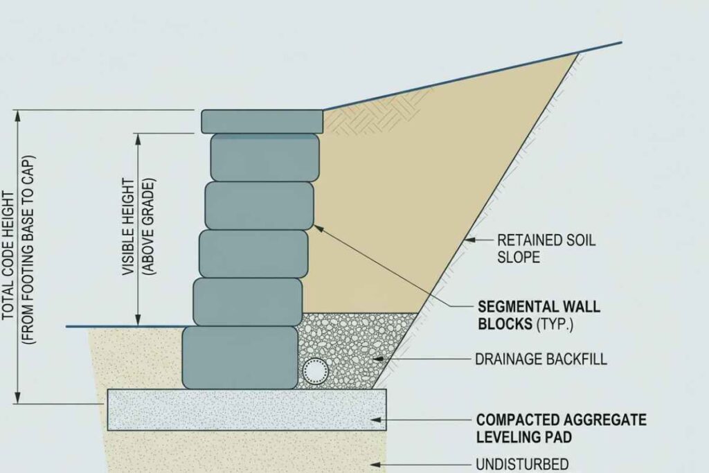
Step 1: Identify the lowest point of the wall structure. For walls on a poured concrete footing, the measurement starts at the bottom of that footing. Segmental retaining walls often sit on a compacted aggregate leveling pad instead of a footing. In that case, the measurement starts at the bottom of the lowest buried block course.
Step 2: Measure vertically to the top of the wall. The measurement ends at the top of the wall cap or the highest course if no cap is installed. Measure plumb, not along the face. A wall with a battered (inward-leaning) face will have a shorter face measurement than its true vertical height.
Step 3: The resulting number is the code height. It does not matter how much of that height is visible above grade. A segmental retaining wall with a standard single-course embedment of 6 inches buries that height below the soil line, but the code counts it.
Step 4: Check the grade on the retained side. Sloped grade behind the wall changes the effective retained height. If the soil continues upward past the top of the wall, the retained height extends to the highest point of grade within the influence zone, not to the wall cap.
A wall that measures 3 feet from footing to cap but retains a slope rising another 2 feet is functioning as a structure managing 5 feet of lateral earth pressure. The code threshold analysis must account for that additional retained soil. The gap between what a homeowner sees standing in front of the wall and what the code actually measures is where most permit miscalculations originate.
Surcharge Conditions That Require Engineering Regardless of Wall Height
The height thresholds covered in the previous section apply only to walls that retain soil and nothing else. The moment anything adds load to the ground behind or above the wall, a separate rule takes over.
A surcharge is any vertical load applied to the retained soil that increases the lateral force acting on the wall. IBC Section 105.2, Item 4 and IRC Section R105.2, Item 3 both state that the permit exemption for walls under 4 feet does not apply when the wall supports a surcharge. The code language is unconditional. A 2-foot wall supporting a surcharge requires the same engineering review as a 6-foot wall with no surcharge.
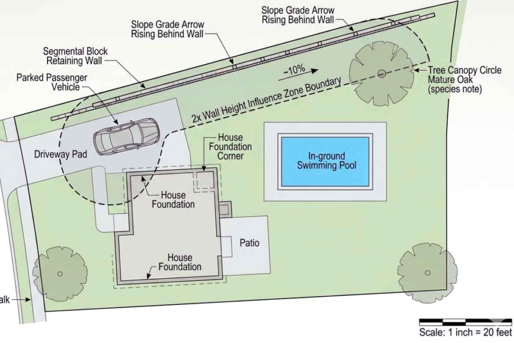
Any load-generating object within 2 times the total wall height from the back face of the wall falls within the wall’s influence zone. The following conditions are the most common residential surcharges that trigger engineering:
- Vehicle loads. Driveways, parking pads, or any surface where vehicles travel or park within the influence zone. A passenger vehicle generates approximately 100 psf of surface load. The wall must be designed for the heaviest vehicle that will use the surface, not the most common one.
- Building foundations. House foundations, porch footings, garage slabs, and deck post footings within 2x the wall height from the wall face. Foundation loads are continuous and permanent, which means the wall carries that additional lateral force for its entire service life.
- Slope above the wall. Retained soil continuing upward past the top of the wall at any grade steeper than 10H:1V (10 feet horizontal for every 1 foot of vertical rise) constitutes a surcharge. The steeper the slope and the closer it begins to the wall face, the greater the additional lateral force the wall must resist.
- Swimming pools and spas. Water weighs 62.4 pounds per cubic foot. A pool or spa within the influence zone adds both the weight of the water and the weight of the structure itself as a surcharge.
- Fence on top of the wall. Wind load on the fence transfers into the wall even when the fence posts are not physically attached to the wall structure. A 6-foot privacy fence in a 90 mph wind zone generates lateral force that a gravity-based wall design does not account for without engineering.
- Large trees. Root growth exerts lateral pressure on the wall face. Trunk weight and wind load on the canopy create overturning forces transmitted through the root system into the retained soil. Tree surcharge evaluation is species- and site-specific, which is why large trees within 2x the wall height of the wall face require individual engineering assessment rather than a general clearance.
Foundation loads and vehicle loads are the two conditions most frequently missed during initial project scoping. A homeowner planning a wall along a driveway edge or downslope from a house foundation often does not recognize that those structures change the engineering requirements for the wall. The 2x rule is a screening threshold, not a safe harbor. Site-specific soil conditions, drainage patterns, and the magnitude of the load can extend the influence zone beyond 2x the wall height.
Tiered Retaining Walls and Combined Height Rules
Building two shorter walls instead of one tall wall does not automatically keep a project below the PE stamp threshold. How the code treats a tiered wall system depends on the horizontal distance between the walls, the relative height of each tier, and whether the upper wall creates a surcharge condition on the lower wall.
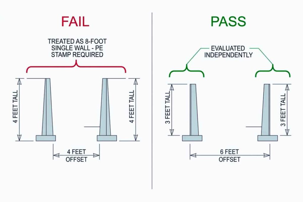
The governing principle is the offset rule. For two tiered walls to be treated as independent structures, the horizontal distance between the back face of the lower wall and the front face of the upper wall must be at least 2 times the height of the lower wall. The upper wall must also be shorter than the lower wall. If both conditions are met, each wall is evaluated independently. If either condition is not met, the two walls are treated as a single structure.
Two 4-foot walls spaced 4 feet apart fail the offset rule. The offset equals 1x the lower wall height, not the required 2x. Under the code, that configuration is a single 8-foot wall requiring a permit, PE-stamped plans, and engineering for the combined height.
Two 3-foot walls spaced 6 feet apart pass. The offset equals 2x the lower wall height. If the upper wall is shorter than or equal to the lower wall, each wall is evaluated at its own height. In St. Louis County, each would still require a permit at the 3-foot threshold, but the engineering analysis treats them separately.
Only one terrace is permitted on a non-engineered wall.
A three-tier system requires PE-stamped plans regardless of individual tier heights or offsets, because the interaction between three retained soil zones exceeds what the offset rule accounts for.
The reason the rule exists is structural. When two walls sit close together, the upper wall’s retained soil falls within the lower wall’s influence zone. The lower wall then carries its own lateral earth pressure plus the surcharge load from the upper wall’s soil mass. Without sufficient horizontal separation, the lower wall experiences forces it was never designed to resist. The offset distance creates enough soil mass between the walls to dissipate the upper wall’s influence before it reaches the lower wall’s failure plane.
Some contractors build multiple short tiers specifically to keep each tier below the permit threshold. This practice does not eliminate the engineering requirement. It redistributes it across structures that are still interacting structurally. If the offset and height conditions are not met, the project is a single wall under the code regardless of how many individual tiers are constructed.
St. Louis County addresses tiered walls through pre-approved master plan retaining wall systems. For projects using an approved manufacturer’s design, SLCO allows double-tiered walls up to 8 feet in total combined height without custom site-specific engineering. The manufacturer’s pre-approved engineering serves as the PE-stamped design, and the master plan number must be quoted on the permit application. Single-tier walls are permitted up to 6 feet under these systems, and any project exceeding these limits or using non-approved products requires custom PE-stamped plans.
Why the 4-Foot Threshold Exists: Lateral Earth Pressure and Wall Physics
The 4-foot threshold is not a bureaucratic round number. It is the height at which the forces acting on a retaining wall exceed what gravity-based residential wall systems can reliably resist without engineering calculations specific to the site.
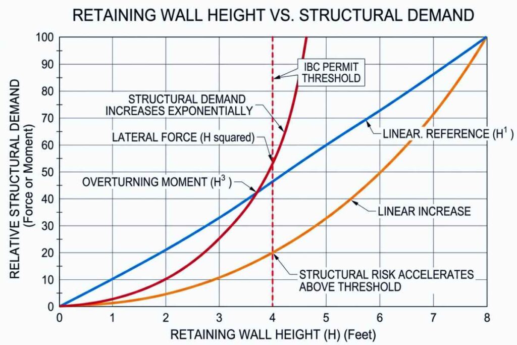
The physics that determines this threshold is non-linear. Lateral earth pressure on a retaining wall is governed by the equation P = K × γ × H, where P is the pressure at any given depth, K is the coefficient of active earth pressure (a function of soil type and friction angle), γ (gamma) is the soil unit weight, and H is the depth from the top of the wall. Pressure at any single point increases linearly with depth. The total lateral force on the wall is calculated by integrating that pressure over the wall’s full height, which produces a force proportional to H squared. The overturning moment, which is the rotational force trying to tip the wall forward, is proportional to H cubed because it factors in the lever arm acting on the base.
Doubling the wall height does not double the structural demand. It quadruples the lateral force and increases the overturning moment by a factor of eight.
For typical soils, the lateral force load is expressed as equivalent fluid pressure measured in pounds per cubic foot. Granular soils like sand and gravel generate 30 to 35 pcf of equivalent fluid pressure. Clay soils generate 55 to 60+ pcf because clay’s lower internal friction angle and water retention characteristics produce greater lateral force at the same depth. At 4 feet of wall height, the total lateral force from clay soil approaches the practical limit of what an unreinforced segmental wall system can resist through self-weight alone.
This is where Missouri’s geology matters. The St. Louis metropolitan area sits on expansive clay soils, classified as CH (high-plasticity clay) and CL (low-plasticity clay) under the Unified Soil Classification System. These soils swell when they absorb water and shrink when they dry. The cyclical expansion and contraction creates seasonal pressure variations on the wall that a gravity-based design built for static loads cannot account for. A wall that holds for a year may begin to lean during the second wet season as the clay cycles through several expansion events.
Hydrostatic pressure compounds the problem. Water weighs 62.4 pounds per cubic foot. When saturated soil sits behind a wall with no drainage system, the water cannot dissipate, and the lateral load on the wall can effectively double. A wall designed for 35 pcf equivalent fluid pressure carrying soil that has become saturated may experience loads closer to 90 to 100 pcf. Clay soils make this worse because they trap water against the wall face and release it slowly.
The code response to these forces is the safety factor requirement. IBC Section 1807.2.3 requires a minimum safety factor of 1.5 against both sliding and overturning. That means the wall’s calculated resistance to each failure mode must be at least 1.5 times the calculated load. A wall designed without engineering has no calculated resistance and no calculated load. There is no way to verify whether the safety factor is met because no one has done the math.
That is the actual function of the 4-foot threshold. Below 4 feet, the forces are low enough that standard residential materials and conventional construction practices typically remain within safe limits even without site-specific calculations. Above 4 feet, the H-squared and H-cubed scaling pushes the loads into territory where assumptions are no longer safe and the math has to be done.
What PE-Stamped Retaining Wall Plans Include

A PE stamp is not the deliverable. The stamp certifies a complete set of structural calculations, construction drawings, and specifications that together demonstrate the wall will perform under the site-specific conditions.
A complete set of PE-stamped retaining wall plans typically includes the following components:
- Structural calculations. The engineer’s analysis of how the wall resists failure: overturning safety factor (minimum 1.5 per IBC 1807.2.3), sliding safety factor (minimum 1.5), bearing capacity against the soil’s allowable load, and global stability analysis evaluating whether the entire soil mass behind and beneath the wall could fail as a unit. The calculations cite the soil parameters, surcharge assumptions, and load combinations used.
- Wall cross-section drawing. The wall in vertical profile: stem height, footing width (heel and toe), embedment depth below grade, reinforcement placement, and the relationship between the wall structure and the retained soil. This is the drawing the field crew builds from.
- Geogrid reinforcement schedule. For reinforced soil walls, the schedule specifies grid type (manufacturer and tensile strength rating), length of each layer, vertical spacing, and connection method to the wall face. Geogrid schedules vary by wall height and soil type, which is why pre-printed manufacturer details cannot substitute for site-specific engineering on walls where reinforcement is required.
- Drainage plan. Perforated pipe location and slope, aggregate drainage envelope dimensions, filter fabric specification, and outlet location. Drainage is the single largest contributor to long-term wall performance and is what protects against the hydrostatic pressure conditions described in the previous section.
- Backfill specification. The soil type permitted behind the wall, the compaction requirements (typically expressed as a percentage of Proctor density), and the maximum lift thickness during placement. The calculated lateral earth pressure assumes specific soil properties. Using the wrong fill invalidates the engineering analysis even if the drawings are followed exactly.
- Site plan. Wall location relative to property lines, required setbacks, existing structures, and utility easements. The site plan is what the building department uses to verify the wall does not encroach on neighbors, easements, or restricted zones.
- Material specifications. Block type (with ASTM C1372 compliance for segmental retaining wall units), required concrete compressive strength for cast-in-place elements, grout requirements where applicable, and aggregate gradation for drainage and base materials.
In St. Louis County, the structural drawings must be sealed by a Missouri registered Professional Engineer or licensed architect, and the structural calculations must also bear the seal. A drawing set without sealed calculations is incomplete under the SLCO Residential Retaining Walls Checklist and will not pass plan review.
What this set of deliverables produces is not just a permit. It is a record of the analysis that justifies the wall’s design at the specific location, in the specific soil, under the specific loads it will carry.
How to Verify a Missouri PE License Before Hiring
A PE stamp on a set of drawings means nothing if the engineer who applied it is not actually licensed. Missouri provides a public verification tool that takes less than two minutes to use, and it should be the first step in evaluating any engineer or any contractor who claims to use one.
Step 1: Go to the Missouri Division of Professional Registration website at pr.mo.gov. The Division is the state agency that maintains license records for all regulated professions in Missouri, including Professional Engineers. The license lookup tool is publicly accessible and requires no account.
Step 2: Search by name or license number. The lookup accepts either the engineer’s full legal name or the Missouri PE license number. Searching by license number returns a single result. Searching by name may return multiple results if the engineer has a common name, in which case the city or firm affiliation listed in the result narrows the match.
Step 3: Confirm the license status is Active. Acceptable statuses for a working PE are Active or Active in Good Standing, and any other status means the engineer is not currently authorized to practice professional engineering in Missouri. Common non-active statuses include Expired, Inactive, Suspended, Revoked, and Surrendered. A stamp applied during a period when the license was not Active does not satisfy the legal sealing requirement.
Step 4: Confirm the discipline covers civil or structural engineering. Missouri PE licenses are issued by discipline. A licensed mechanical engineer or electrical engineer is a licensed PE in Missouri but is not authorized to design structural retaining walls. The discipline relevant to retaining wall design is civil engineering, with structural engineering as a sub-discipline. The license record shows the discipline the engineer was licensed to practice.
Step 5: Request a copy of the engineer’s current license and insurance certificate before engaging. The license lookup confirms the credential exists on the day the search is performed. A physical copy of the license document and a certificate of professional liability insurance address the gap between verification and project completion. Insurance certificates also indicate whether the engineer’s policy covers structural design work specifically.
The same verification applies when a contractor claims an engineer reviewed the plans. A contractor stating that they “have an engineer” should be able to provide the engineer’s full legal name and Missouri PE license number on request. If they cannot, the engineering claim cannot be verified, and no actual PE accountability exists for the design. RSMo 327.191 makes practicing or offering to practice professional engineering without a license a Class A misdemeanor, which means a contractor representing engineering work without a licensed PE behind it is exposed to legal liability beyond the structural risk.
A two-minute search at pr.mo.gov resolves whether the credential is real before any money changes hands.
St. Louis County Retaining Wall Permit Process with PE-Stamped Plans
The permit process in St. Louis County is sequential. Each step depends on the previous one being complete, and skipping a step usually means restarting from earlier in the sequence. The full process from zoning approval to permit closure typically spans several weeks for a standard residential wall, longer for complex projects or projects requiring revisions during plan review.
Here is what the process looks like when PE-stamped plans are required.
Step 1: Get zoning approval from the project site municipality. This step happens before SLCO is involved. The municipality where the property sits has its own zoning code, setback requirements, and sometimes its own retaining wall standards that may differ from county-level rules. The municipality stamps or signs the site plan to confirm the wall location complies with local zoning, and that stamped site plan becomes part of the SLCO submittal package. Skipping this step is the most common cause of delayed permit applications, because SLCO will not process a permit without the municipal zoning approval already in place.
Step 2: Complete the SLCO electronic building permit application. St. Louis County uses an electronic submission system for residential building permits. The application requires the property owner’s information, the contractor’s information (if applicable), the project description, and the wall dimensions. The application is signed electronically.
Step 3: Submit the site plan and PE-sealed structural documents. The submittal package includes the municipally-stamped site plan showing wall location, property lines, and setbacks, along with the PE-sealed structural drawings and the PE-sealed structural calculations. Both the drawings and the calculations must bear the engineer’s seal. Drawings without sealed calculations, or calculations without sealed drawings, will not pass intake.
Step 4: SLCO plan review. A plan reviewer in the Department of Public Works examines the submittal for code compliance, structural adequacy, and completeness. Review timelines vary by current workload and project complexity. Simple walls move faster than tall walls, walls with surcharges, or walls with unusual site conditions. If the reviewer identifies issues, the application returns to the applicant with comments that must be addressed before review can continue.
Step 5: Pull the approved permit and schedule the footing inspection. Once plan review is complete, the permit is issued and the construction phase begins. The footing inspection must be scheduled and passed before any concrete is poured or any leveling pad is placed. This is the inspection that verifies the base of the wall is constructed to the approved plans, and it is non-negotiable: a wall with a footing that was never inspected cannot be closed out at the final inspection stage.
Step 6: Complete construction and schedule the final inspection. The final inspection verifies the wall was built to the approved plans, that drainage is in place, and that backfill was completed correctly. The final inspection contact number for SLCO is 314-615-5184.
Step 7: Submit the engineer of record’s construction observation letter. This is the step most homeowners do not know about until they reach it. The PE who sealed the original drawings (the engineer of record) must visit the site during or after construction and issue a written letter confirming that the wall was built in substantial compliance with the stamped plans. SLCO requires this letter to close the permit. Without it, the permit remains open indefinitely, which can complicate property transactions, refinancing, and any future permit applications on the same property.
There is an alternative path for projects that fit within SLCO’s pre-approved master plan retaining wall systems. For walls using an approved manufacturer’s pre-engineered design, the manufacturer’s stamped plans serve as the structural submittal. Single-tier walls under these systems are permitted up to 6 feet in total height, and double-tier walls up to 8 feet in total combined height. The master plan number must be quoted on the permit application. Projects that fit the master plan criteria skip the custom engineering step but still require zoning approval, plan review, footing inspection, and final inspection.
The engineer of record letter requirement is the step that catches most projects off guard.
Costs of PE-Stamped Wall Engineering vs. Costs of Wall Failure
The cost question is the one most homeowners ask first when they learn engineering is required. The relevant comparison is not engineering cost versus zero cost. It is engineering cost versus the cost of resolving a wall built without engineering that either failed or triggered enforcement action.
The figures below reflect general market ranges for residential retaining wall projects in the St. Louis metro area. Specific costs vary by wall height, soil conditions, number of tiers, site access, and the engineer or contractor selected.
| Cost Category | With PE-Stamped Plans | Without Engineering |
|---|---|---|
| Engineering plans | $500 to $3,000 | $0 |
| Geotechnical report (if required) | $1,500 to $4,000 | $0 |
| Wall demolition (if failure occurs) | Not applicable | $3,000 to $10,000+ |
| Site regrading and excavation | Not applicable | $2,000 to $8,000+ |
| Wall rebuild to engineered standards | Not applicable | $10,000 to $50,000+ |
| Property damage liability | Covered by engineering verification | Personal liability exposure |
| Insurance coverage for the wall | Typically intact | Commonly excluded for unpermitted structures |
| Code enforcement | None | Stop-work order, fines, mandatory removal possible |
PE plan costs range from $500 to $3,000 depending on wall complexity, height, and number of tiers. A simple single-tier wall under 6 feet in standard soil sits at the lower end. A taller wall, a tiered system, or a wall in expansive clay with surcharge conditions sits at the higher end. Geotechnical reports add $1,500 to $4,000 when the jurisdiction requires soil testing or when the engineer determines the site needs verification before design.
The cost of resolving a failed wall is where the comparison shifts. Demolition runs $3,000 to $10,000 or more depending on size, materials, and access. Site regrading and excavation adds $2,000 to $8,000. The rebuild itself, now constructed to engineered standards because the failure makes the engineering requirement unavoidable, runs $10,000 to $50,000 or more. The total cost of the failure pathway can reach several multiples of what the original engineered project would have cost.
Property damage liability is the cost component most homeowners overlook. When an unengineered wall fails and damages adjacent property, undermines a neighbor’s foundation, or causes injury, the property owner who built the wall is personally liable for the damages. This liability is not eliminated by the absence of a permit. It is often increased by it, because building without required permits and engineering can be cited as evidence of negligence in civil claims.
Insurance coverage operates as a separate consideration from liability.
Homeowner’s insurance policies commonly exclude coverage for structures built without required permits or engineering. The exclusion language varies by carrier and policy, but the general principle is that unpermitted structural work falls outside the scope of standard property coverage. When a wall built without a permit fails and damages the home, the carrier may deny the claim entirely.
Code enforcement is a separate cost track. A wall built without a required permit can trigger a stop-work order during construction, fines, and in some cases a mandatory removal order requiring demolition even if the wall has not failed.
The decision is not whether to spend money. It is whether to spend it on calculation and verification before construction or on demolition and reconstruction after a problem develops.
When a Retaining Wall Under 4 Feet Still Needs Engineering Review
The 4-foot threshold is a starting point, not a finish line. Several conditions override the height exemption and require engineering even for walls that fall well below it. A homeowner who confirms their wall is under 4 feet has answered only the first question in the analysis.
The following conditions require engineering review regardless of wall height:
- Any surcharge present. Driveways, building foundations, swimming pools, fences, slopes, and large trees within the influence zone all trigger the engineering requirement under IBC 105.2 Item 4, regardless of how short the wall is. The surcharge override is the most common condition that catches sub-threshold walls. The full list of surcharge conditions is covered in the surcharge section earlier in this article.
- Property line proximity (St. Louis County). SLCO requires a permit for any retaining wall located within a horizontal distance equal to its own height from a property line, even if the wall is under the 3-foot residential threshold. A 2-foot wall built 18 inches from a property line requires a permit because the wall sits within its own height of the line. This rule exists because a wall failure that close to a property boundary creates immediate risk of damage to neighboring property, and the property owner who built the wall is personally liable for that damage regardless of which side of the line the wall sits on.
- Tiered configuration. Two short walls close together may be treated as a single tall wall under the offset rule. Two 3-foot walls spaced less than 6 feet apart are evaluated as a single 6-foot wall and require engineering even though each individual tier is below the threshold. A homeowner planning multiple short tiers specifically to stay under the threshold should verify the offset distance against the rule before assuming the tiers are independent. Full mechanics are covered in the tiered walls section earlier in this article.
- Expansive clay soil with poor drainage. St. Louis metro sits on CH and CL clay soils that swell when wet and shrink when dry. This cyclical pressure cycle is not accounted for in gravity-based designs built for static loads. A 3-foot wall in expansive clay with no drainage system can experience seasonal pressure variations that exceed the design assumptions for a static-load wall, even at sub-threshold height.
- Proximity to water sources. Walls near ponds, creeks, irrigation lines, downspout discharge points, or known drainage paths require drainage engineering regardless of height. Saturated soil behind a wall doubles the lateral load through hydrostatic pressure, and water sources within the influence zone create chronic saturation conditions that a standard short wall design does not address.
- Slope above the wall. Any slope steeper than 10H:1V behind the wall constitutes a surcharge that triggers engineering review. The retained soil mass continuing upward past the top of the wall adds lateral force that the wall’s footing-to-cap height does not reflect.
- Non-standard materials. Walls built from materials without manufacturer-published load tables, such as railroad ties or stacked stone without mortar, should be reviewed by an engineer regardless of height. The structural calculations that justify height exemptions for standard segmental retaining wall units rely on published material properties. Materials without those properties have no calculated basis for the exemption.
Sub-threshold does not mean exempt. It means the height alone does not require engineering, and any other condition that affects structural performance can put the wall back into the engineering category.
Garden Wall vs. Retaining Wall: Why the Distinction Determines Engineering Requirements
The terms “garden wall” and “retaining wall” are often used interchangeably in residential conversations, but they describe two structurally distinct things, and the distinction determines whether engineering requirements apply at all.
A retaining wall laterally supports soil and resists lateral earth pressure. A garden wall is a freestanding structure that does not retain soil on either side. Retaining walls are subject to IBC 105.2 height thresholds, surcharge rules, and PE stamp requirements when conditions trigger them. Garden walls are not, because they carry no retained soil load.
The test that determines which category a wall falls into is single and binary: does the wall hold back a grade change on one side? If the answer is yes, the wall is a retaining wall under IBC 202, regardless of height, material, decorative appearance, or what the installer or product label calls it. A 16-inch landscape edge that holds back 12 inches of soil to create a raised planting bed is a retaining wall. A 4-foot decorative stone wall sitting on flat ground between two yards with the same grade on both sides is a garden wall.
The most common misclassification involves short walls built to create raised garden beds, planting areas, or terraced landscaping. These walls look ornamental and are often installed as part of a landscape design rather than as a structural element. They still retain soil. The IBC and IRC do not distinguish between walls built for structural purposes and walls built for decorative purposes when both retain a grade change. The functional definition governs.
A wall that transitions from freestanding to soil-retaining along its length is a retaining wall for the retaining portion. The freestanding portion does not require engineering analysis. The retaining portion does, and the engineering review applies to the wall section that holds back soil regardless of how the wall is described as a whole.
Misclassifying a retaining wall as a garden wall does not change its regulatory status. It only delays the recognition that engineering review may be required.
Why the PE Stamp Question Has More Than One Answer
The PE stamp requirement in Missouri is not a single number. It is the result of three regulatory layers (IBC baseline, SLCO local amendment, RSMo 327.181 state law) interacting with the specific conditions of the project site.
Height triggers the requirement at 4 feet under the IBC and 3 feet under the SLCO residential checklist. But height is only the first variable. Surcharge loads, tiered configurations, property line proximity, expansive clay soil, water source proximity, and non-standard materials each operate as independent triggers that can require engineering for walls well below any height threshold.
The practical answer for any specific wall depends on what the wall is, where it sits, what loads it carries, and what soil it retains.
A 3-foot wall with no surcharge in standard soil away from a property line may be exempt under most Missouri jurisdictions. A 2-foot wall built 18 inches from a property line in expansive clay near a downspout discharge point is not exempt anywhere in St. Louis County.
The 4-foot threshold is a screening tool, not a finish line. It tells the property owner where to start the analysis, not where it ends.
The full analysis requires looking at every condition that affects how the wall will perform under the loads it will actually carry.