Retaining wall engineering standards govern how earth-retaining structures resist lateral earth pressure, surcharge loads, and water loads while maintaining stability against sliding, overturning, bearing failure, and global slope failure. The discipline combines geotechnical analysis of soil behavior with structural design of the wall system itself. The governing code stack includes IBC 1807 for building-site walls, ASCE 7-22 load combinations, AASHTO LRFD for transportation-adjacent structures, NCMA standards for segmental retaining wall systems, and ACI 318 for reinforced concrete stems and footings. State licensure rules determine when a Professional Engineer seal is required — in Missouri, that framework runs through RSMo Chapter 327, with RSMo 327.181 defining the practice of professional engineering and RSMo 327.191 establishing the licensure requirement. This page covers the full engineering framework: governing codes and load categories, PE trigger thresholds, wall system classification, lateral earth pressure analysis, stability checks, footing embedment, drainage and backfill specifications, and construction document requirements.
What Do Retaining Wall Engineering Standards Actually Require?
Retaining wall engineering standards require structural analysis against lateral earth pressure, surcharge, and hydrostatic load using load combinations from ASCE 7, with design methods drawn from IBC 1807 for buildings, AASHTO LRFD for transportation structures, and system-specific standards like NCMA for segmental walls or ACI 318 for reinforced concrete. The governing document is determined by project type and jurisdiction, not designer preference. IBC 1807.2 governs walls on building sites the local building department’s adopted IBC cycle controls which version applies.
Transportation-adjacent walls follow AASHTO LRFD Bridge Design Specifications, 9th Edition (2020). Segmental systems follow the NCMA Design Manual for Segmental Retaining Walls, 3rd Edition. Reinforced concrete stems and footings fall under ACI 318. Standards can stack: a cast-in-place cantilever wall on a building site runs under IBC 1807.2 for overall design and ACI 318 for the concrete elements simultaneously.
Every retaining wall resists five load categories. Lateral earth pressure is the primary case, using one of three coefficients: active (Ka) when the wall moves away from retained soil, at-rest (K0) when the wall is restrained against movement, and passive (Kp) at the toe where soil resistance counters sliding. Surcharge loads add pressure beyond what soil alone generates. A driveway or structure within a horizontal distance equal to the retained height H falls inside the influence zone a residential driveway typically contributes 250 psf minimum, converted to lateral pressure and added to the earth pressure calculation.
When drainage fails, saturated retained soil transmits full hydrostatic head as a horizontal load against the wall face. That load can match or exceed the lateral earth pressure the wall was designed to carry. Drainage is an engineering input, not a finishing detail. Seismic increments apply where ASCE 7-22 Chapter 11 design categories require it. Construction equipment surcharge during backfill must also be included. ASCE 7-22 load combinations govern how these categories combine into the design load case.
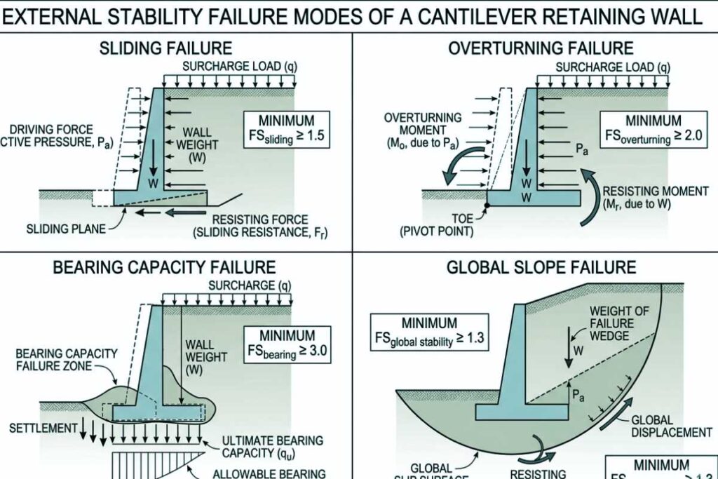
Minimum factors of safety define the margin between calculated resistance and calculated demand. Against sliding, FS 1.5 — base friction must clear 1.5 times total horizontal force. Against overturning, FS 2.0. Overturning carries the higher threshold because rotation about the toe develops faster than sliding and leaves less time for detection before distress occurs. Against bearing capacity failure, FS 3.0, reflecting soil strength uncertainty beneath a loaded foundation. Global slope stability requires FS 1.3 to 1.5 per USACE EM 1110-2-1902, depending on loading condition. These are allowable stress design values. LRFD projects under AASHTO use load and resistance factors instead, but the structural intent is the same.
When Does a Retaining Wall Require a Licensed Engineer?
A retaining wall generally requires a licensed engineer when it exceeds 4 feet in height measured from bottom of footing to top of wall per IBC 1807.2, when any surcharge is applied regardless of height, when the site is in an identified slope hazard zone, or when state licensure law specifies a lower threshold; in Missouri, RSMo 327.181 defines the practice of professional engineering and RSMo 327.191 establishes the PE licensure requirement and exemption framework that determines when a PE seal is required.
- Height: Wall exceeds 4 feet of unbalanced fill, bottom of footing to top of wall, per IBC 1807.2.
- Surcharge: Any surcharge load is present, regardless of wall height.
- Slope hazard: Site is in an identified slope hazard or instability zone.
- State licensure: Missouri RSMo 327.181 and 327.191 establish the PE requirement and exemption framework for the project jurisdiction.
The 4-foot threshold marks the height at which lateral earth pressure typically exceeds what an unreinforced gravity section can resolve without analysis. IBC 1807.2.4 defines unbalanced fill for threshold measurement: the dimension runs from the bottom of the footing to the top of the retained soil, not finished grade.
IBC 1807.2.3 applies a stricter standard to rubble stone retaining walls. These walls lack the tensile continuity of reinforced or mortared systems and require engineering at lower heights than the general threshold. IRC R404.4 carries the same 4-foot trigger into residential construction.
Local amendments in some Missouri municipalities set the engineering trigger below the IBC default. The adopted code cycle and local amendments control, not the IBC threshold alone.
Any surcharge eliminates the height exemption entirely. A driveway, structure foundation, sloped backfill, vehicle load, or adjacent foundation within the influence zone constitutes a surcharge condition regardless of wall height.
The standard quantification method converts surface surcharge to equivalent fluid pressure acting laterally against the wall. Two distribution approaches apply depending on load geometry: the 1-foot surcharge strip methodology for concentrated or linear loads, and the 2:1 influence distribution rule for spread loads projecting down through the retained zone.
When surcharge is omitted from an unreinforced wall calculation, the lateral load the wall actually carries exceeds the load it was sized to resist. That is the failure condition, not a conservative design margin.
Missouri PE licensure is governed by RSMo Chapter 327. RSMo 327.181 defines the practice of professional engineering, and structural design of a retaining wall falls within that definition.
RSMo 327.191 establishes the licensure requirement and exemption framework. The agricultural structure exemption applies only when the wall serves an agricultural use on agricultural land. The employee-under-supervision condition applies only when the work is performed under direct supervision of a licensed Missouri PE who takes responsible charge. Neither exemption applies to residential or commercial retaining wall projects.
An out-of-state PE seal does not satisfy RSMo 327.191 for Missouri projects. The licensing authority is the Missouri Board for Architects, Professional Engineers, Professional Land Surveyors and Professional Landscape Architects under RSMo Chapter 327.
How Is Lateral Earth Pressure Calculated for Retaining Wall Design?
Lateral earth pressure is calculated using soil unit weight (γ), retained height (H), and an earth pressure coefficient selected by wall behavior. The coefficient is active (Ka) when the wall is free to rotate, at-rest (K0) when the wall is fixed against movement, or passive (Kp) when the wall is being pushed into the retained soil. Selecting the wrong coefficient produces an incorrect design, not a conservative one.
Ka applies when the wall can move away from the retained soil. This is the typical condition for a properly designed gravity or cantilever wall. Sufficient wall rotation, on the order of 0.001H to 0.004H depending on soil type, mobilizes the active pressure state and reduces lateral load below at-rest levels.
K0 applies when the wall is restrained against movement. Basement walls tied into floor slabs and bridge abutments tied into superstructure cannot rotate freely. The soil behind them never reaches the active state. The full at-rest pressure acts against the wall face.
K0 is always higher than Ka for the same soil. Using Ka where K0 governs produces a wall sized for a lower load than it will actually carry. Kp applies in the opposite direction. When the wall is pushed into the soil at the toe, the soil mobilizes passive resistance against the wall face. Kp is typically three to ten times Ka depending on friction angle.
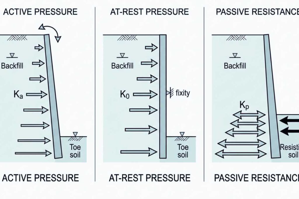
That ratio is what makes toe embedment a meaningful contributor to sliding resistance. Passive pressure is a resistance term, not a load term.
Friction angle (φ) is the soil property that appears in every pressure coefficient calculation. It represents the internal shearing resistance of the soil mass and is determined from geotechnical investigation: direct shear tests, triaxial tests, or presumptive values from soil classification for preliminary design. The value of φ drives Ka, K0, and Kp. Assuming it without testing on an engineered wall introduces error into every downstream load calculation.
The three analysis methods determine how Ka is derived from soil properties.
Rankine: p = Ka × γ × H, where Ka = tan²(45 + φ/2) for active pressure. Rankine assumes a vertical wall face, horizontal backfill surface, and no friction between wall and soil. Rankine is conservative by design because ignoring wall friction overstates the lateral force the wall must resist. Most gravity wall preliminary designs and standard cantilever wall calculations run on Rankine without issue.
Coulomb: accounts for wall friction (δ), inclined backfill (β), and sloped wall face (α). The basic Coulomb Ka equation takes the form: Ka = sin²(α + φ) divided by sin²(α) × sin(α – δ) × (1 + √(sin(φ + δ) × sin(φ – β) divided by sin(α – δ) × sin(α + β)))². It produces a lower Ka than Rankine when wall friction is present because the friction component redirects some lateral force downward. Sloped backfill always requires Coulomb or an equivalent method. Rankine cannot account for the additional lateral pressure that sloped fill generates. SRW systems with battered face angles also require Coulomb.
Mononobe-Okabe: the canonical pseudostatic seismic method. It adds a seismic coefficient (kh) to the static active pressure calculation. The total active thrust including seismic component is PAE = 0.5 × γ × H² × KAE, where KAE is derived from ground acceleration and soil friction angle. Applied where ASCE 7-22 seismic design categories or applicable local seismic provisions require it.
What Stability Checks Must Every Engineered Retaining Wall Pass?
Every engineered retaining wall must pass four external stability checks: sliding, overturning, bearing capacity, and global slope stability, plus internal stability checks specific to the wall system. USACE EM 1110-2-2502 governs external stability for earth-retaining structures. FS minimums below are allowable stress design values. LRFD projects under AASHTO use load and resistance factors instead.
- Sliding: Horizontal force versus frictional resistance at the wall base. FS 1.5 minimum. Failure produces lateral wall movement. A shear key cast into the footing increases passive resistance where base friction is insufficient.
- Overturning: Driving moment about the toe versus resisting moment from wall self-weight and heel soil bearing. FS 2.0 minimum. Failure produces rotation about the toe.
- Bearing capacity: Actual base pressure versus allowable bearing capacity of the founding soil. FS 3.0 minimum. Failure produces foundation settlement or punch-through. Footing depth selection is covered in the H3 below.
- Global slope stability: Circular or non-circular slip surface passing through or behind the wall. FS 1.3 to 1.5 per USACE EM 1110-2-1902 depending on loading condition.
This is the check most consistently overlooked on sloped sites. A wall that passes the first three can still fail if the slope behind it is unstable. Global stability failure does not give progressive warning the way sliding does.
External checks confirm the wall holds its position. They say nothing about whether the structural elements inside it can carry the loads assigned to them.
Internal stability checks address that gap.
- Cantilever walls: Stem flexure and shear per ACI 318. The stem acts as a vertical cantilever fixed at the footing. Development length governs rebar embedment required to transfer full tensile force into the concrete at the stem base. Heel and toe designed separately for their respective pressure distributions.
- SRW walls: Three checks at each geogrid elevation. Tensile rupture confirms the grid carries the assigned horizontal force. For pullout resistance, grid length embedded in compacted backfill must develop sufficient friction. Facing connection capacity confirms the block-to-grid connection transfers load. Connection failure is the controlling condition on taller SRW systems and typically results in the facing separating from the reinforced soil mass. All three must pass at every elevation.
- MSE walls: Reinforcement tensile capacity and pullout resistance follow the same framework as SRW. Facing element connection is checked separately because MSE panels transfer load differently than modular SRW blocks.
A complete analysis requires all seven checks. External stability alone is not engineering review.
What Are Typical Footing Depth and Embedment Requirements?
Retaining wall footings are embedded to satisfy three concurrent drivers: minimum toe embedment, frost protection, and bearing capacity adequacy. The governing depth is the deepest of the three, not the shallowest.
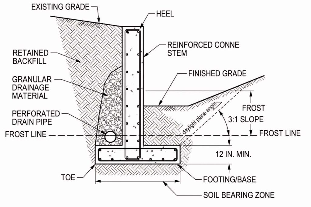
- Toe embedment: IBC 1809.4 requires a minimum 12-inch embedment below finished grade at the wall face. This prevents exposure and undermining of the footing as grade erodes or shifts at the toe.
- Frost protection: IBC 1809.5 requires the footing to bear below the local frost line to prevent heave cycling. The St. Louis region typically runs 30 inches, with some local adoptions extending to 36 inches. The design frost depth is controlled by the adopted code cycle of the specific jurisdiction, not the IBC default alone.
- Bearing capacity adequacy: Where native soils are soft, the footing must go deeper than toe protection or frost minimums alone require. The base pressure at the founding elevation must fall within the allowable bearing capacity of the material present. IBC Table 1806.2 provides presumptive bearing values for soil classification. Geotechnical investigation provides tested values for engineered walls.
On sloped sites, footing depth must also satisfy the daylight plane condition under IBC 1809.4. The bottom of the footing must maintain a minimum horizontal distance to the slope face, typically expressed as 1H:1V or as specified by the local building department. A footing that satisfies frost and toe protection requirements can still produce shallow bearing failure if the daylight plane cuts through the bearing zone.
How Do Drainage and Backfill Specifications Affect Wall Performance?
Drainage and backfill specifications determine whether the wall performs as designed: a wall analyzed without hydrostatic pressure fails when drainage is omitted because water loading can double the lateral force, and a wall designed for granular backfill fails when clay is placed behind it because the design friction angle and drainage assumptions no longer hold.
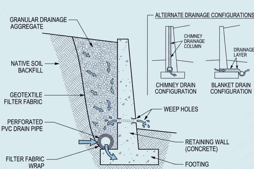
Required drainage components on an engineered wall:
- Drainage aggregate zone: Two configurations apply depending on wall type and site condition. A chimney drain runs as a vertical drainage column directly behind the wall face, used where drainage must be concentrated at the wall face. A blanket drain runs as a horizontal drainage layer at the wall base, used where water must be intercepted across the full retained zone before it reaches the wall. Both use ASTM No. 57 stone per ASTM D448 aggregate size classifications: clean, free-draining, and resistant to fines migration. Minimum aggregate zone width is 12 inches for SRW systems per NCMA Design Manual. Cast-in-place walls follow the geotechnical report specification.
- Perforated drain pipe at base: 4-inch PVC wrapped in filter fabric, placed at the bottom of the drainage aggregate zone to collect and route water away from the wall base.
- Weep holes or outlet pipe to daylight: spaced every 8 to 10 feet on cast-in-place walls. Water that enters the drainage zone must have a clear path out. Without an outlet, the aggregate zone saturates and hydrostatic pressure builds regardless of how well the drainage layer was installed.
- Filter fabric between drainage aggregate and native soil: prevents fines from migrating into the drainage zone over time. A drainage aggregate zone that has silted up provides no drainage benefit. The fabric is what keeps the zone functional over the wall’s service life.
When drainage components are omitted, hydrostatic pressure can double the lateral force the wall was designed to resist. That load condition was never included in the design analysis.
Backfill material and compaction govern the load the wall actually carries in service.
- Granular backfill: sand, gravel, or crushed stone with a specified gradation. Friction angle and drainage behavior are predictable for granular material. The design assumptions hold.
- Compaction: 95 percent standard Proctor per ASTM D698, in lifts of 8 to 12 inches. Under-compaction reduces confinement pressure on the retained soil mass, increases differential settlement behind the wall, and can cause facing rotation or outward displacement on SRW systems.
- Native clay substitution: lower friction angle increases lateral earth pressure beyond design assumptions. Hydrostatic loading follows because clay drains poorly and the drainage system was not sized for that condition. During freeze cycles, frost susceptibility generates heave force against the wall face.
Design assumptions that do not appear on the drawings are not enforceable in the field. When drawings specify only “backfill” without naming the material, gradation, and compaction requirement, the specification cannot be enforced during construction. The consequence is a wall built to different load assumptions than those used in the engineering analysis.
What Do Construction Documents for an Engineered Retaining Wall Include?
Construction documents for an engineered retaining wall include a sealed structural drawing set with plan, elevation, and typical section; a geotechnical report or referenced soil parameters; design calculations documenting the load cases and factor-of-safety results; reinforcement schedule; drainage detail; specifications for backfill and compaction; and a PE seal from an engineer licensed in the project jurisdiction.
A complete engineered design package contains nine elements.
- Plan view: shows wall alignment, horizontal geometry, and grading at the site. A plan view without grading contours cannot confirm that the wall height and retained fill shown in the cross-section match actual site conditions.
- Elevation: shows wall height variation along the alignment. Retaining walls are rarely uniform in height. A wall designed to a single representative height when actual height varies along the alignment produces under-designed segments at the taller portions. The elevation is what confirms every segment has been designed for its actual retained height.
- Typical cross-section: shows wall geometry, footing dimensions, reinforcement layout, and drainage configuration. For permit submittal, reinforcement callouts must name bar size, spacing, and cover. A cross-section submitted for permit without reinforcement callouts is not a construction document.
- Reinforcement schedule: lists bar designations, lengths, bend details, and quantities for the full wall. The schedule is a standalone document element separate from the cross-section callouts. It is what a contractor uses to order and place steel, and what an inspector uses to verify installation.
- Drainage detail: shows the drainage aggregate zone configuration, drain pipe location and size, filter fabric placement, and outlet location. The drainage detail must match the drainage assumptions in the design calculations.
- Backfill and compaction schedule: names the backfill material, gradation, and compaction standard explicitly. A schedule that specifies only “granular fill” without gradation and compaction requirements is not enforceable in the field.
- Geotechnical basis: either references the geotechnical report by document number and date, or states assumed soil parameters explicitly on the drawings. Parameters that do not appear on the drawings cannot be verified during construction or after a failure.
- Calculation summary: documents the load cases analyzed, stability checks performed, and the factor-of-safety result for each check. The load inputs must appear alongside the FS results: lateral earth pressure calculation, surcharge derivation, hydrostatic pressure assumption, and seismic increment where applicable. An independent reviewer must be able to trace from load input to FS result for each stability check. A summary showing only final FS values is not a verifiable calculation package.
- PE seal: carries the engineer’s name, state of licensure, and license number. The seal confirms the engineer of record holds an active license in the project jurisdiction. Jurisdictions that require PE seals on permit submittals also require a valid license number on the seal.
A design package missing any of these elements is not a basis for construction or permit submittal.
How to Evaluate a Retaining Wall Design for Code Compliance
Evaluate a proposed retaining wall design by verifying five points in order: governing code is cited and current, height and surcharge trigger engineering per jurisdiction, stability calculations show all required factors of safety, drainage and backfill specs appear on drawings, and the document set carries a PE seal from an engineer licensed in the project state. If any of the five is missing or unclear, the design is not code-compliant and requires revision before construction.
- Governing code: Confirm which standard governs the project and that the edition is current for the jurisdiction’s adopted cycle. IBC projects run on the edition the local building department has adopted. AASHTO LRFD projects run on the edition the state DOT enforces. A design citing a superseded edition may not satisfy current permit requirements.
- PE trigger: Confirm the wall scope triggers PE involvement under the applicable rules. Check height against the 4-foot unbalanced fill threshold per IBC 1807.2. Check whether any surcharge is present. In Missouri, confirm the engineer of record holds a Missouri PE license under RSMo 327.191, applying the practice definition in RSMo 327.181. An out-of-state seal does not satisfy Missouri’s licensure requirement.
- Stability calculations: Confirm the calculation summary shows results for all required checks. Sliding FS at or above 1.5. Overturning FS at or above 2.0. Bearing capacity FS at or above 3.0. Global slope stability FS at or above 1.3.
That covers external stability. Internal stability checks must also be present for the wall type: stem flexure and shear for cantilever walls, geogrid rupture and pullout and facing connection for SRW systems, reinforcement tensile and pullout for MSE walls.
- Drainage and backfill on drawings: Confirm the drainage aggregate zone, drain pipe, filter fabric, and weep holes or outlet pipe appear on the drawings with dimensions and specifications. Confirm the backfill schedule names the material, gradation, and compaction standard. Drainage and backfill details that appear only in a narrative report and not on the construction drawings are not enforceable in the field.
- PE seal: Confirm the seal carries the engineer’s name, license number, and state of licensure. Confirm the license is active in the state where the wall will be built. A seal without a license number or from an engineer not licensed in the project state is not a compliant submittal.
A design that clears all five points has addressed the core compliance requirements. Other project-specific conditions, AHJ requirements, or plan reviewer determinations may still apply.