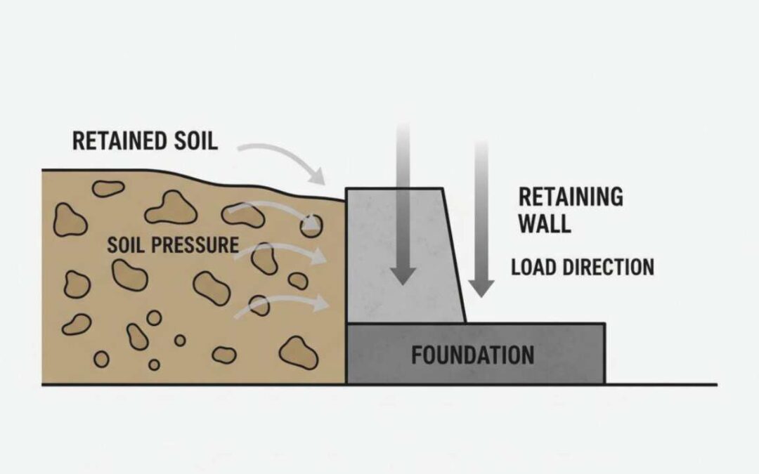
Retaining wall engineering is the geotechnical and structural design process used to hold back soil by controlling lateral earth pressure, surface loads, groundwater pressure, and foundation response. The wall itself is only one part of the system. Soil strength, drainage behavior, base support, and load conditions determine how the structure must be designed.
A retaining wall resists horizontal pressure created by retained soil and anything placed above that soil. That pressure increases as wall height increases, as slopes steepen, or as additional loads such as driveways, buildings, or stored materials act on the ground behind the wall. Water trapped in the soil can also create hydrostatic pressure that adds significant force against the structure.
Engineering analysis converts those site conditions into design decisions. Soil properties, groundwater levels, wall geometry, drainage provisions, and available construction space determine which wall system is appropriate and how large structural elements must be. Stability checks and structural design calculations verify that the wall can resist sliding, overturning, foundation pressure, and internal structural demand under the expected loads.
Retaining walls appear simple from the surface, but their performance depends on how the soil, water, and structural elements interact below grade. That interaction is what retaining wall engineering evaluates and controls.
What Retaining Wall Engineering Actually Means
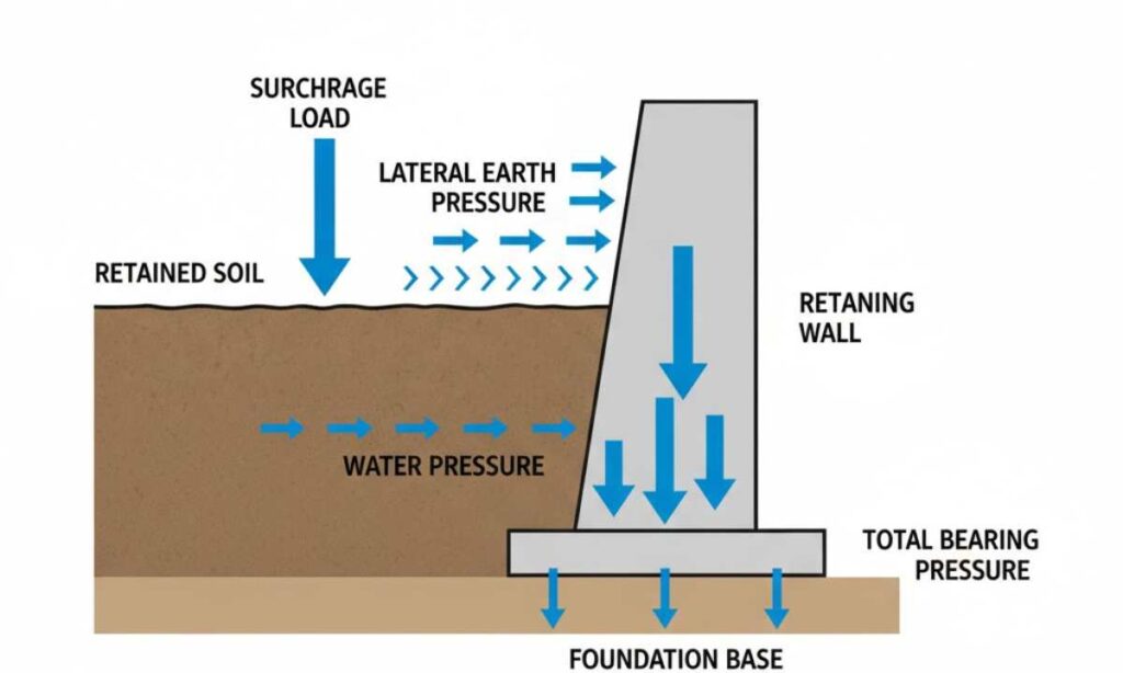
Diagram showing how lateral earth pressure, surcharge loads, and water pressure move through a retaining wall system.
Source: rwpsllc.com
Want to use this diagram? You can reference it with attribution.
Retaining wall engineering refers to the combined geotechnical and structural process used to design walls that safely hold back soil while transferring loads into the ground. Soil mechanics evaluates how soil weight, internal friction, and moisture conditions influence the lateral pressure acting on the wall. Structural design determines how the wall and its supporting elements resist those forces so the structure can avoid sliding, rotation, or foundation settlement. The wall performs as intended only when both systems are evaluated together.
Walls that hold back soil are not all designed under the same engineering conditions. Low garden or grade-separation walls may be constructed without formal analysis of soil pressure or foundation response. Engineered retaining walls differ because their geometry, reinforcement, drainage provisions, and foundation requirements are determined through calculations that evaluate lateral earth pressure, surcharge loading, and bearing capacity of the supporting soil.
Wall performance depends on how several interacting systems behave below ground. Soil properties determine the magnitude and distribution of pressure acting against the wall, drainage conditions influence whether hydrostatic pressure develops, and the supporting foundation soil must resist the forces transferred through the wall structure. Incorrect assumptions about any of these conditions can allow the wall to shift, rotate, or place excessive pressure on the supporting soil.
Retaining wall engineering evaluates the interaction between the retained soil mass, groundwater behavior, wall structure, and supporting foundation. Loads from soil weight, water pressure, and surcharge sources move through the wall components and into the supporting soil. Depending on these conditions, different structural approaches may be used, including engineered structural wall systems designed to handle higher loads and constrained site conditions.
Retaining Wall Design Standards and Safety Assumptions
The design of a retaining wall depends on the loads acting on the structure, the strength of the soil supporting it, and the regulatory requirements governing construction. Engineering standards provide calculation methods for estimating lateral earth pressure, evaluating foundation response, and determining the structural forces acting on the wall. These methods guide how wall dimensions, reinforcement, and drainage provisions are established so the wall can resist movement caused by soil pressure and applied loads.
Engineers apply factors of safety to account for uncertainty in soil properties, groundwater behavior, and loading conditions. Stability checks evaluate whether the wall can resist sliding along its base, rotation caused by overturning forces, and excessive pressure on the supporting soil. Structural calculations then verify that wall components and reinforcement can resist bending and shear created by those loads.
Local building codes and project-specific conditions also influence the final design. Many jurisdictions require engineering review or stamped drawings when retaining walls exceed height thresholds or support additional loads such as slopes, driveways, or nearby structures. Permit triggers establish regulatory oversight, but engineering judgment still determines how soil conditions, drainage, and structural resistance are addressed in the final design.
Sources
National Concrete Masonry Association (NCMA). Design Manual for Segmental Retaining Walls, 3rd Edition.
Braja M. Das and Khaled Sobhan. Principles of Geotechnical Engineering. Cengage Learning.
Joseph E. Bowles. Foundation Analysis and Design. McGraw Hill.
Missouri Engineering Practice Act, §327.011 RSMo.
Factors That Affect Retaining Wall Design
Retaining wall design begins with evaluating the ground conditions and loads that act on the structure. If soil strength, groundwater conditions, or wall geometry are misjudged, the resulting pressures can exceed the wall’s resistance and lead to sliding, rotation, or foundation settlement. Soil properties, groundwater behavior, wall geometry, and surrounding site constraints determine the magnitude of lateral pressure and how those forces move through the wall and into the supporting ground.
Soil properties influence both the magnitude of lateral earth pressure and the resistance available to support the wall foundation. Groundwater conditions determine whether drainage systems are required to prevent hydrostatic pressure from developing behind the wall. Wall geometry such as height, base width, and embedment depth controls how the structure resists sliding and overturning forces. Soil mechanics and foundation engineering texts such as Principles of Geotechnical Engineering by Braja M. Das and Khaled Sobhan describe the pressure relationships and soil parameters used in these calculations.
Sloping terrain, nearby structures, and limited construction space also influence how a retaining wall must be designed. Backfill material and compaction level affect how water moves through the retained soil and how forces transfer from the wall into the foundation soil. Retaining wall engineering therefore begins with evaluating these site-specific inputs before wall type, geometry, and reinforcement are established.
Soil Properties Used in Retaining Wall Engineering
Soil properties determine how much pressure acts against the wall and how much resistance the ground can provide to support the structure. Geotechnical analysis uses measured soil parameters to estimate earth pressure, foundation support capacity, and potential settlement behavior.
Soil unit weight describes the weight of soil per unit volume and directly affects the magnitude of lateral pressure applied to the wall. As retained soil height increases, the weight of soil above the base increases the horizontal pressure acting on the structure.
The internal friction angle of soil describes the resistance created by interlocking soil particles. Higher friction angles reduce active earth pressure and increase the passive resistance that develops in front of the wall foundation. Cohesion represents bonding forces between soil particles, but cohesive strength is often treated conservatively because moisture changes can significantly reduce its reliability.
Bearing capacity describes the ability of the supporting soil to resist the vertical loads transferred through the wall foundation. If the supporting soil cannot carry those loads, the wall foundation may settle or rotate even when the structural components remain intact. Methods for evaluating these soil parameters are described in geotechnical design references such as Foundation Analysis and Design by Joseph E. Bowles.
Wall Geometry That Controls Stability
Wall geometry determines how the structure balances the forces created by retained soil and surcharge loads. Dimensions such as wall height, base width, and embedment depth influence how the wall resists sliding, overturning, and excessive foundation pressure.
Wall height is the primary factor controlling lateral earth pressure. As retained soil height increases, the horizontal force applied to the wall increases significantly. Taller walls therefore require larger base dimensions, reinforcement, or alternative structural systems to maintain stability.
Base width influences both sliding resistance and the pressure distribution beneath the wall foundation. A wider base increases friction along the foundation and spreads the load over a larger area of supporting soil. Heel and toe dimensions within the base also affect the resisting moment that prevents overturning.
Embedment depth improves confinement of the foundation soil and increases passive resistance in front of the wall. Some walls are constructed with a slight backward lean known as batter, which shifts the wall weight toward the retained soil and increases resistance to overturning.
Site Conditions That Change Retaining Wall Design
Ground conditions and surrounding site features can significantly change the loads acting on a retaining wall. Retained slope angle, nearby structures, property boundaries, and groundwater conditions all influence the assumptions used in the design.
Sloping ground behind the wall increases the mass of retained soil and raises the lateral pressure acting on the structure. Buildings, driveways, and stored materials near the top of the wall introduce surcharge loads that add additional force to the retained soil.
Property boundaries and excavation limits restrict how wide the wall foundation can be constructed. When space for a wide base is unavailable, engineers may select alternative wall systems such as reinforced soil walls or sheet pile structures that require less footprint.
Groundwater conditions also affect wall behavior. Water accumulating behind a wall increases hydrostatic pressure and can reduce the shear strength of certain soils. Drainage provisions and appropriate backfill materials are therefore necessary when groundwater or surface runoff is present.
Loads on a Retaining Wall and How They Move Through the System
Soil retained behind a wall applies horizontal pressure that the structure must resist and transfer safely into the ground. Additional forces can come from surface loads, groundwater pressure, seismic activity, or temporary construction equipment. If these loads are underestimated, the resulting forces can exceed the wall’s resistance and lead to sliding, overturning, or foundation settlement, which is a primary reason behind why retaining walls fail under drainage and load pressure.
The primary load acting on most retaining walls is lateral earth pressure created by the weight of retained soil. The magnitude of this pressure depends on soil unit weight, wall height, backfill slope, and the friction characteristics of the soil. Classical soil mechanics methods used to estimate these pressures are described in Principles of Geotechnical Engineering by Braja M. Das and Khaled Sobhan.
Surcharge loads, groundwater pressure, and construction forces can act on the retained soil at the same time as lateral earth pressure. Buildings, driveways, stored materials, or sloping terrain increase the vertical stress within the retained soil mass. The additional vertical stress increases the horizontal pressure acting against the wall and must be included when calculating the total design load.
Forces applied behind the wall must move through structural components before they reach the supporting ground. The wall face, structural stem, base slab, reinforcement, or reinforced soil mass carry these loads until they are transferred into the supporting soil. This movement of forces through the structure is known as the load path, and it determines whether the wall can resist sliding, overturning, and excessive foundation pressure.
Earth Pressure in Retaining Wall Design
Soil retained behind a wall creates lateral pressure that increases with depth. The weight of the soil mass above a given point causes the pressure near the base of the wall to be greater than near the top. Engineers estimate this pressure using earth pressure theories developed in soil mechanics.
Two commonly used methods are the Rankine and Coulomb earth pressure theories described in Principles of Geotechnical Engineering by Braja M. Das and Khaled Sobhan. These methods estimate how soil weight, friction, and backfill geometry influence the forces acting on the wall.
Active earth pressure represents the condition that develops when the wall moves slightly away from the retained soil and the soil mass expands. Passive earth pressure develops in soil located in front of the wall foundation when that soil is compressed. At-rest earth pressure represents the pressure that exists when the wall does not move enough to mobilize active conditions.
Engineers select the appropriate pressure state based on wall type, expected movement, and soil properties. The chosen pressure condition establishes the lateral force used in stability checks and structural design calculations.
Surcharge Loads Behind Retaining Walls
Loads applied above the retained soil increase the pressure acting against a retaining wall. These additional loads are referred to as surcharge loads because they add weight to the soil mass behind the wall.
Buildings, foundations, driveways, and vehicle traffic can apply uniform or concentrated loads to the retained ground. The added weight increases the vertical stress within the soil, which increases the horizontal pressure acting against the wall.
Sloping ground above the wall produces a similar effect because the depth and weight of retained soil increase toward the back of the slope. Stored materials or equipment placed near the wall can also increase the load applied to the retained soil mass.
These surcharge conditions increase the lateral forces that the wall must resist and therefore affect both stability calculations and structural design.
Water Pressure Behind Retaining Walls
Water trapped behind a retaining wall can produce hydrostatic pressure that acts independently of soil weight. This pressure increases with water depth and can significantly increase the force applied to the wall.
Groundwater movement, rainfall infiltration, or blocked drainage paths can allow water to accumulate behind the wall. When this occurs, hydrostatic pressure acts directly against the structure and adds to the lateral earth pressure created by the soil.
Soil mechanics and foundation engineering references such as Foundation Analysis and Design by Joseph E. Bowles describe how water pressure and seepage influence earth pressure assumptions and stability calculations. Because water pressure can increase quickly, retaining wall systems typically include drainage layers and outlets that prevent hydrostatic pressure from building behind the wall.
Seismic and Construction Loads on Retaining Walls
Retaining walls may also be subjected to loads that occur during seismic events or construction activities. These loads differ from the static forces produced by soil and water.
Earthquake motion can temporarily increase the lateral pressure acting on retained soil. Seismic earth pressure is often evaluated using methods such as the Mononobe Okabe approach described in geotechnical engineering literature. These calculations determine the additional forces generated when ground acceleration occurs during seismic activity.
Construction equipment used to compact backfill can also apply temporary loads to the wall during installation. Vibratory rollers or compactors placed close to the wall can create short term lateral pressure that exceeds the pressure expected under normal conditions. Engineers evaluate these temporary and seismic loads when checking wall stability and determining safe construction practices.
How Load Transfer Works in a Retaining Wall
Loads acting on retained soil must move through the wall structure before they reach the supporting ground. This sequence of force transfer is known as the load path.
Soil pressure, surcharge loads, and hydrostatic pressure act on the retained side of the wall. These forces push against the wall face or reinforced soil mass and create bending, shear, and tension forces within the structural components.
In rigid concrete walls, loads transfer from the wall stem into the base slab and then into the supporting soil beneath the foundation. In reinforced soil systems such as mechanically stabilized earth walls, loads are distributed through layers of reinforcement that extend into the retained soil mass.
The final stage of load transfer occurs at the foundation interface, where the supporting soil resists vertical pressure and sliding forces. Structural and geotechnical design methods described in Foundation Analysis and Design by Joseph E. Bowles evaluate whether the foundation soil can safely support those loads.
Retaining Wall Types Compared by Height, Soil, and Space
Different retaining wall systems are used depending on wall height, soil conditions, available space, and construction constraints. Each system manages soil pressure using a different structural approach.
Gravity walls rely primarily on their own weight to resist lateral earth pressure. Reinforced concrete cantilever walls resist soil pressure using structural bending resistance in the wall stem and base slab. Reinforced soil systems distribute loads through layers of reinforcement embedded within the retained soil mass.
The wall system selected for a project must match the loads acting on the structure, the strength of the supporting soil, and the construction space available at the site. Taller walls often require structural reinforcement or engineered systems that can resist larger bending forces. Weak foundation soils or limited construction space may require systems that distribute loads differently or require a smaller foundation footprint.
Engineering references such as the NCMA Design Manual for Segmental Retaining Walls describe the procedures used to design and evaluate these retaining wall systems.
Gravity vs Cantilever Retaining Walls
Gravity retaining walls rely primarily on their mass to resist lateral soil pressure. The weight of the wall and the width of its base provide the resisting forces needed to prevent sliding and overturning. These walls typically require a relatively wide footprint because stability depends on wall weight.
Cantilever retaining walls use reinforced concrete elements to resist soil pressure through structural action. The wall stem and base slab work together to create a lever system that transfers loads into the foundation soil.
Wall height and available space often determine which system is appropriate. Gravity walls can perform well for lower heights where sufficient base width is available. Cantilever walls become more efficient at greater heights because structural reinforcement can resist larger bending forces without requiring as much mass.
Cantilever vs Counterfort Retaining Walls
Cantilever walls rely on bending resistance in the wall stem and base slab to resist lateral pressure. As wall height increases, bending forces in these elements also increase.
Counterfort retaining walls add triangular structural supports called counterforts between the wall stem and base slab. These supports tie the wall elements together and reduce bending demand on the wall stem.
Counterfort systems are often used for taller retaining walls where bending forces would otherwise require very thick concrete sections. Standard cantilever walls are typically simpler and more practical for moderate wall heights.
MSE vs Concrete Retaining Walls
Mechanically stabilized earth walls use layers of reinforcement placed within the retained soil to create a reinforced soil mass. Facing panels or segmental blocks provide a stable wall surface while the reinforcement layers carry tensile forces within the soil.
Concrete retaining walls rely on rigid structural elements such as reinforced stems and base slabs to resist soil pressure. These walls transfer loads through structural members rather than through a reinforced soil mass.
Footprint requirements, soil conditions, and construction access often determine which system is appropriate. MSE walls can distribute loads over a wider area of reinforced soil, while concrete walls rely on structural components and foundation support.
When a Sheet Pile Retaining Wall Is Used
Sheet pile retaining walls consist of interlocking steel sheets driven into the ground to form a continuous vertical barrier. These walls resist soil pressure primarily through bending resistance and embedment into the supporting soil.
Sheet pile systems are commonly used where excavation space is limited and a wide wall foundation cannot be constructed. Their narrow footprint allows installation in confined areas where gravity or cantilever walls may not be feasible.
Soft ground conditions or deep excavations may also favor sheet pile systems because the embedded sheets can develop resistance from the surrounding soil. Their structural behavior differs from gravity, cantilever, and reinforced soil walls because stability depends heavily on embedment depth and bending resistance.
Backfill and Drainage Design Behind a Retaining Wall
The soil placed behind a retaining wall influences both the loads acting on the structure and the movement of water through the retained ground. When drainage layers or backfill materials do not allow water to escape, hydrostatic pressure can increase the lateral load acting on the wall. Backfill selection, drainage layers, and compaction conditions therefore affect both groundwater behavior and the forces transferred from the retained soil mass to the wall.
Engineered retaining walls use specified backfill materials rather than relying on soil excavated from the site. Native soils often contain clay or fine particles that restrict water movement. When these soils remain behind the wall, water can accumulate and generate hydrostatic pressure that was not assumed in the design calculations. Geotechnical references such as Foundation Analysis and Design by Joseph E. Bowles describe how groundwater conditions and soil permeability influence earth pressure and wall stability.
Free-draining granular backfill allows water to move downward toward drainage pipes and outlets rather than building pressure against the wall. The amount of fine material within the backfill also affects drainage behavior. High fines content can clog drainage zones or filter layers, allowing water to accumulate behind the structure.
Backfill compaction also affects wall performance. Compacted soil increases shear strength and improves the ability of the backfill to transfer loads into the wall system. At the same time, excessive compaction forces during construction can temporarily increase lateral pressure on the wall. For reinforced soil systems such as mechanically stabilized earth walls, the backfill must also meet reinforcement compatibility requirements so geogrid layers can develop the friction needed to resist pullout. Guidance for backfill selection and drainage design is provided in engineering references such as the NCMA Design Manual for Segmental Retaining Walls.
Backfill Materials Used Behind Retaining Walls
Backfill materials used behind retaining walls are selected based on drainage behavior, soil strength, and compatibility with the wall system. Each material influences groundwater movement and the lateral soil pressure acting on the structure.
Select granular backfill is commonly used behind many retaining walls because its particle size distribution allows predictable drainage and compaction behavior. Granular soils with low fines content allow water to move through the backfill rather than accumulating against the wall face.
Drainage backfill is often placed directly behind rigid retaining walls. This material typically consists of clean gravel or crushed stone that forms a permeable zone where water can move freely toward drainage pipes or outlets.
Mechanically stabilized earth walls use reinforced fill that must meet specific strength and gradation requirements so the soil can interact properly with reinforcement layers such as geogrids. The friction between the reinforcement and the soil allows the reinforced mass to resist lateral pressure.
Native soil excavated from the site can be reused as backfill only when soil composition and drainage characteristics meet the design requirements. Soils with high clay content or poor permeability can trap water behind the wall and increase hydrostatic pressure.
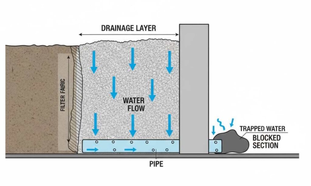
Retaining Wall Drainage Systems
Drainage systems control the movement of groundwater and surface water behind a retaining wall. These systems prevent water pressure from building in the retained soil and help maintain the design assumptions used for earth pressure calculations.
Perforated drainage pipes are commonly installed at the base of the wall to collect water moving through the backfill. The pipe directs the collected water to an outlet where it can discharge away from the structure.
Drainage gravel or crushed stone placed behind the wall creates a permeable zone that allows water to flow toward the drainage pipe. This drainage layer reduces the likelihood that water will accumulate directly against the wall.
Filter fabrics or geotextiles are often used between drainage layers and surrounding soil. These materials allow water to pass through while preventing fine soil particles from migrating into the drainage gravel or pipe system.
Drain outlets and discharge paths determine whether collected water can exit the drainage system. If the system cannot discharge water effectively, hydrostatic pressure can still build behind the wall even when drainage materials are present.
Retaining Wall Design Calculations
Retaining wall design calculations translate soil conditions and loading assumptions into the wall dimensions and structural resistance required to support the retained ground. Soil properties, groundwater conditions, wall geometry, and surcharge loads determine the forces applied to the structure. Engineering analysis determines whether those forces will produce sliding, overturning, or excessive pressure on the supporting soil.
The calculation sequence begins with estimating earth pressure acting on the retained side of the wall. Soil unit weight, friction angle, and backfill slope determine the earth pressure coefficient used in the analysis. Methods described in geotechnical engineering references such as Principles of Geotechnical Engineering by Braja M. Das and Khaled Sobhan are commonly used to determine these pressure relationships.
Additional loads are then included in the design load calculation. Surface surcharge from structures or vehicles increases vertical stress within the retained soil mass. Hydrostatic pressure may be considered when groundwater conditions or drainage limitations allow water to accumulate behind the wall. Seismic and construction loads are also evaluated when site conditions or construction methods can temporarily increase lateral pressure.
The loads acting on the wall generate horizontal forces and overturning moments that tend to rotate the structure about its base. Vertical forces from wall weight and surcharge loads produce reactions within the foundation soil. Engineering calculations determine the base reactions and pressure distribution beneath the footing so the supporting soil can safely carry the load. Procedures for evaluating foundation response and base pressure distribution are described in references such as Foundation Analysis and Design by Joseph E. Bowles.
Once the forces acting on the wall are established, engineers determine the structural demand within the wall system. Bending forces in the wall stem, shear forces within structural members, and tension forces within reinforcement layers are derived from the load path created by the retained soil mass. These demands determine the required wall geometry, reinforcement layout, and foundation dimensions needed to support the calculated loads.
Retaining Wall Stability Checks
Retaining wall stability checks verify that the calculated loads and wall geometry can be resisted by the structure and the supporting soil. These checks determine whether the wall can remain stable under expected loading conditions without sliding, rotating, or overstressing the foundation soil. Engineers apply factors of safety so the available resistance in the soil and wall system exceeds the driving forces produced by earth pressure, surcharge loads, and groundwater conditions.
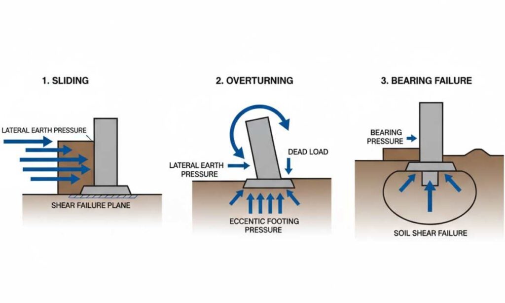
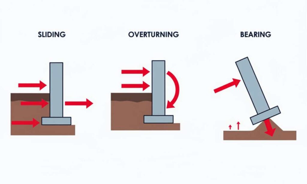
External stability checks evaluate the ability of the wall to resist large-scale movement. Sliding checks verify that friction and shear resistance along the wall base are sufficient to resist horizontal soil pressure. Overturning checks evaluate whether the resisting moment created by the wall weight and base geometry exceeds the overturning moment caused by lateral earth pressure and surcharge loads.
Foundation response is also evaluated because the soil supporting the wall must carry the vertical forces transferred through the structure. Bearing capacity analysis determines whether the foundation soil can resist the applied pressure without shear failure. Engineers also evaluate base pressure distribution to determine whether uneven loading could cause rotation or settlement of the wall. These procedures are described in geotechnical engineering references such as Foundation Analysis and Design by Joseph E. Bowles.
Additional stability checks apply to reinforced retaining wall systems and sloped sites. Reinforced soil structures must resist internal tension and pullout forces within the reinforcement layers. In sites where retaining walls support slopes or hillsides, engineers also evaluate global slope stability to determine whether the retained soil mass could fail independently of the wall. Design guidance for these stability evaluations appears in engineering standards such as the NCMA Design Manual for Segmental Retaining Walls.
Serviceability checks evaluate wall behavior under normal loading conditions rather than ultimate failure conditions. Engineers assess predicted wall movement, potential cracking in rigid wall systems, and long-term deformation in reinforced soil structures to determine whether the wall will maintain acceptable performance over time.
Sliding Check for Retaining Walls
Sliding checks evaluate whether the wall can resist horizontal movement along its base. Lateral earth pressure acting on the retained side of the wall produces a horizontal force that tends to push the structure outward.
Resistance to sliding is provided primarily by friction between the wall base and the supporting soil. The magnitude of this resistance depends on base width, foundation soil strength, and the interface friction between the footing and the soil.
Embedment depth and passive soil resistance in front of the wall can also contribute to sliding resistance. Engineers compare the driving horizontal forces with the resisting forces at the base to determine whether the factor of safety against sliding is adequate.
Overturning Check for Retaining Walls
Overturning checks evaluate whether lateral loads could rotate the wall about the front edge of its base. Lateral earth pressure and surcharge loads produce an overturning moment that tends to tip the wall outward.
The resisting moment comes from the weight of the wall and the position of that weight relative to the base. Increasing wall weight or base width increases the resisting moment that counteracts overturning forces.
Engineering analysis compares the overturning moment generated by lateral loads with the resisting moment produced by wall weight and geometry. The resulting ratio establishes the factor of safety against rotation.
Bearing, Settlement, and Foundation Response Checks
The soil beneath the wall must support the vertical loads transferred through the foundation. Bearing capacity analysis determines whether the foundation soil can resist the applied pressure without shear failure.
Engineers also examine the pressure distribution beneath the wall base. Lateral loads shift the pressure distribution toward the toe of the wall, creating uneven loading conditions. If the pressure exceeds the allowable bearing capacity of the soil, the foundation may experience excessive settlement or rotation.
Settlement analysis evaluates whether the supporting soil will compress under load. Differential settlement across the wall base can create structural stress and wall movement even when overall stability conditions appear acceptable.
Weak subgrade conditions may require foundation preparation such as soil replacement, compaction improvement, or other ground stabilization methods.
Internal Stability Checks for Reinforced Retaining Walls
Reinforced retaining wall systems rely on structural elements within the retained soil mass to resist lateral pressure. In mechanically stabilized earth walls, reinforcement layers such as geogrids carry tensile forces generated by soil pressure.
Internal stability checks determine whether the reinforcement can resist these tensile forces without rupture. Engineers also evaluate pullout resistance to determine whether the reinforcement layers can develop sufficient friction with the surrounding soil.
Spacing, length, and strength of reinforcement layers determine how effectively the reinforced soil mass resists lateral pressure acting on the wall system.
Global Stability Checks for Retained Slopes
Retaining walls constructed on sloping sites must also consider the stability of the broader soil mass. The retained slope behind the wall may fail along a deep slip surface that extends beyond the wall structure.
Global stability analysis evaluates the potential movement of the entire soil mass surrounding the wall. Engineers analyze possible slip surfaces and determine whether the factor of safety against slope failure is sufficient.
Geotechnical engineering methods for slope stability analysis are described in references such as Principles of Geotechnical Engineering by Braja M. Das and Khaled Sobhan.
Serviceability Checks for Retaining Wall Movement
Serviceability checks evaluate the performance of a retaining wall under normal operating conditions rather than ultimate failure conditions. Even when a wall satisfies stability requirements, excessive movement or deformation can create structural or functional problems.
Engineers assess predicted wall displacement, potential cracking in rigid wall systems, and long-term deformation in reinforced soil structures. Excessive movement can indicate that soil pressures or foundation conditions exceed the limits assumed during design.
Serviceability evaluation helps determine whether the wall will remain structurally stable while maintaining acceptable levels of movement and cracking over time.
Structural Design of a Retaining Wall
Structural design establishes how the wall stem, footing, and reinforcement resist the forces produced by retained soil and surcharge loads. After earth pressure and stability calculations define the forces acting on the structure, engineers determine how those forces create bending moments, shear forces, and tensile stresses within the wall components.
In rigid retaining walls, the wall stem and base footing form the primary structural members that resist these forces. Lateral earth pressure produces bending in the wall stem, while vertical forces from wall weight and surcharge loads transfer through the footing into the supporting soil. Structural design establishes the required thickness of the wall stem and base slab and the reinforcement needed to resist the calculated bending and shear forces.
Reinforcement is placed where tensile stresses occur within the concrete section. Concrete provides high compressive strength but limited resistance to tension, so steel reinforcement carries the tensile forces produced by bending. Structural design procedures described in references such as Reinforced Concrete: Mechanics and Design by James K. Wight and James G. MacGregor define how bending moments and shear forces determine reinforcement size and placement.
The structural behavior of a retaining wall varies with the selected wall system. Reinforced concrete walls resist soil pressure through bending action in the wall stem and footing. Reinforced soil systems transfer loads through layers of reinforcement embedded within the soil mass. Structural design therefore follows the load path created by retained soil pressure and the structural response of the selected wall type.
Reinforcement Design in Concrete Retaining Walls
Reinforced concrete retaining walls use steel reinforcement to resist the tensile forces created by lateral earth pressure. When soil pressure pushes against the wall stem, one side of the concrete section develops tension while the opposite side remains in compression.
Reinforcement is positioned within the tension zone of the wall section so the steel can carry the tensile forces generated by bending. The required reinforcement area is determined from the bending moment calculated for the wall stem.
The footing must also resist structural forces. The base slab carries vertical loads transferred from the wall stem while resisting bending caused by soil pressure acting on the footing. Reinforcement within the footing therefore differs from the reinforcement used in the wall stem because the structural forces acting on these elements are different.
Structural design standards such as ACI 318, Building Code Requirements for Structural Concrete, provide procedures used to determine reinforcement spacing, bar size, and development length for reinforced concrete retaining walls.
Reinforcement Design in Reinforced Soil Walls
Reinforced soil retaining walls use reinforcement layers embedded within the retained soil mass rather than relying on a rigid concrete wall section. Materials such as geogrids or steel strips extend horizontally into the backfill and interact with the surrounding soil through friction and mechanical interlocking.
These reinforcement layers carry tensile forces generated by lateral soil pressure. The reinforced soil mass resists soil pressure through interaction between the soil and reinforcement layers, where the soil provides compressive support and the reinforcement provides tensile resistance.
Layer spacing, reinforcement length, and tensile capacity determine how effectively the reinforced soil mass resists the lateral forces produced by the retained soil. Design procedures for reinforced soil systems are described in engineering references such as the NCMA Design Manual for Segmental Retaining Walls.
How Engineers Design a Retaining Wall Step by Step
Retaining wall design progresses through a defined engineering sequence that begins with site investigation and continues through load evaluation, structural design, and final stability verification. Each stage produces the soil properties, load estimates, and structural requirements needed to develop the wall geometry and reinforcement layout.
Engineers first determine the soil conditions and groundwater behavior where the wall will be built. These conditions control the earth pressure acting on the wall and the ability of the supporting soil to resist foundation loads. After soil properties are established, engineers estimate the loads acting on the wall, select an appropriate wall system, and develop preliminary wall dimensions.
The preliminary design is then evaluated for stability and structural resistance. Sliding, overturning, bearing capacity, and internal reinforcement behavior are checked to confirm that the wall can resist the calculated loads. Once the structural configuration is confirmed, drainage and backfill details are specified so groundwater conditions behind the wall remain consistent with the assumptions used during the design calculations.
This sequence reflects the engineering procedures used in geotechnical and structural design practice and is described in references such as Principles of Geotechnical Engineering by Braja M. Das and Khaled Sobhan and the NCMA Design Manual for Segmental Retaining Walls.
Site Investigation and Soil Testing
Retaining wall design begins with investigation of the soil and groundwater conditions at the construction site. Soil borings or test pits determine soil layering, soil type, and the depth of competent bearing material.
Samples collected during drilling are tested in a laboratory to determine engineering properties such as soil unit weight, friction angle, cohesion, and permeability. These measured properties are used to calculate earth pressure and evaluate the strength of the foundation soil supporting the wall.
Groundwater levels are recorded during the investigation because water conditions influence earth pressure assumptions and drainage design. These geotechnical parameters are used directly in the calculations that determine wall loads and foundation response.
Load and Pressure Modeling
After soil conditions are defined, engineers estimate the loads acting on the retaining wall. Earth pressure created by the retained soil mass produces the primary lateral force on the structure.
Additional loads are identified from conditions above and behind the wall. Surcharge loads may come from buildings, driveways, or sloping terrain above the retained soil. Groundwater conditions determine whether hydrostatic pressure must be included in the design analysis. Seismic loading and temporary construction loads may also be evaluated depending on project requirements.
These loads are evaluated together to determine the total forces acting on the wall and the supporting soil.
Wall Type Selection and Geometry Development
After the loading conditions are established, engineers select a retaining wall system that fits the soil conditions and construction constraints present at the site. Wall height, foundation soil strength, groundwater conditions, and available construction space influence the selection of wall type.
The selected wall system determines how the structure resists soil pressure. Gravity walls rely primarily on mass and base width, while cantilever walls resist pressure through bending action in reinforced concrete elements. Reinforced soil systems transfer loads through reinforcement layers embedded within the backfill.
Preliminary wall dimensions are then established from the calculated loads. Wall height, base width, embedment depth, and reinforcement layout are selected so the wall can resist sliding, overturning, and foundation pressure.
Design Checks and Structural Sizing
Once preliminary dimensions are established, engineers evaluate the wall for stability and structural resistance. External stability checks verify resistance to sliding and overturning, while bearing capacity analysis confirms that the foundation soil can support the applied loads.
Structural design establishes the thickness of the wall elements and the reinforcement required to resist bending and shear forces. These calculations ensure that wall components can transfer loads from the retained soil to the foundation soil.
Internal stability checks are also performed for reinforced soil systems to verify reinforcement strength, spacing, and pullout resistance.
Backfill and Drainage Detailing
The final stage of retaining wall design establishes the drainage and backfill configuration behind the wall. These details ensure that groundwater conditions during construction and long-term service remain consistent with the assumptions used in the design calculations.
Drainage systems typically include perforated pipes, drainage gravel, and outlet paths that allow water to exit from behind the wall. Filter fabrics or geotextiles are often used to prevent fine soil particles from entering drainage layers.
Backfill specifications define the soil type, compaction level, and filter compatibility required behind the wall. Proper backfill and drainage design prevents hydrostatic pressure from building behind the structure and supports the stability conditions established during the engineering analysis.
Common Causes of Retaining Wall Failure
Retaining wall failure occurs when the forces produced by retained soil, water pressure, or surcharge loads exceed the resisting capacity of the wall structure and the supporting soil. Failures develop when drainage conditions, soil strength, load assumptions, or wall geometry differ from the conditions used in the design calculations. These differences increase lateral pressure, reduce available resistance, or change how loads transfer through the wall and into the foundation soil.
Poor drainage is one of the most common causes of retaining wall failure. Water trapped behind a wall creates hydrostatic pressure that acts in addition to the lateral pressure from the retained soil. This additional pressure increases the horizontal force acting on the wall. If drainage systems become blocked or if free-draining backfill is not installed, water pressure can push the wall outward and increase the likelihood of sliding or overturning. Case studies documented in geotechnical engineering literature such as Foundation Analysis and Design by Joseph E. Bowles describe many failures associated with uncontrolled groundwater conditions.
Inadequate wall geometry can also reduce stability. Walls with insufficient base width or embedment depth may not develop enough resisting force to counteract lateral soil pressure. A narrow base reduces sliding resistance, while shallow embedment limits passive resistance and confinement at the front of the wall. Under these conditions, the wall may lean outward or rotate as soil pressure increases.
Weak foundation soils create another common failure mechanism. If the soil beneath the wall cannot support the applied load, excessive settlement may occur. Uneven settlement beneath the footing can shift the pressure distribution toward one side of the base and cause the wall to rotate or tilt. In severe cases, foundation soil may experience bearing capacity failure when the applied pressure exceeds the soil’s shear strength.
Backfill material and compaction quality also influence the forces acting on the wall. Backfill with excessive fines or poor drainage properties can retain water and increase soil pressure behind the wall. Inadequate compaction can allow the retained soil mass to settle over time, changing the load distribution acting on the wall and increasing lateral pressure.
Additional loads placed near the top of the wall can also lead to failure if they are not included in the design calculations. Structures, vehicles, sloping terrain, or stored materials can create surcharge loads that increase the horizontal pressure acting on the wall. Temporary construction loads during backfilling and compaction can also produce forces that exceed the wall’s capacity if these conditions are not considered during design.
Retaining wall failures often develop when multiple conditions increase load or reduce resistance at the same time. Poor drainage combined with weak foundation soils or underestimated surcharge loads can create forces that exceed the capacity of the wall structure or supporting soil.
Signs a Retaining Wall Has a Structural Problem
Visible changes in a retaining wall often occur when soil pressure, groundwater conditions, or foundation support differ from the conditions assumed during design. Movement, cracking, or drainage staining can indicate that the wall is experiencing increased lateral pressure, foundation movement, or water accumulation behind the structure.
A leaning retaining wall can indicate rotation caused by overturning forces or settlement beneath the foundation. Lateral soil pressure pushes against the retained side of the wall, and if the resisting forces provided by wall weight and base width are insufficient, the wall may rotate outward. Uneven settlement beneath the base can also produce rotation that causes the wall to lean.
Bulging or outward displacement in the wall face can indicate increased lateral pressure within the retained soil mass. This condition may develop when drainage behind the wall becomes restricted or when backfill soil settles or compacts unevenly over time. Elevated soil pressure or deformation within reinforced soil systems can push the wall face outward, often appearing as signs of wall movement from lateral pressure.
Cracking in rigid retaining walls may indicate structural stress or foundation movement. Vertical or diagonal cracks can form when bending forces exceed the capacity of the wall section or when uneven settlement introduces additional stress within the concrete. Cracks may also appear when reinforcement does not provide sufficient resistance to tensile forces created by soil pressure.
Drainage staining, wet areas, or seepage emerging through the wall can indicate that water is accumulating behind the structure. Water trapped within the backfill can create hydrostatic pressure that increases the load acting on the wall. Mineral staining or persistent moisture along the wall face often signals that drainage paths are restricted or that groundwater is moving through the retained soil.
Surface settlement above the wall can indicate compression of backfill or supporting soil beneath the retained ground. Settlement can change the pressure distribution acting on the wall and may also indicate inadequate compaction or weak subgrade conditions behind the structure.
When a Retaining Wall Needs Engineering and Permits
Retaining wall engineering is required when wall height, loading conditions, or site constraints create forces that must be evaluated through structural and geotechnical analysis. Building codes establish conditions where professional design and permitting are required so the wall can be analyzed for stability, structural resistance, and foundation support before construction.
Wall height commonly triggers engineering review and building permits. As wall height increases, the lateral earth pressure acting on the structure increases as well. For example, the International Residential Code (IRC) requires engineering design for retaining walls that retain more than four feet of soil measured from the bottom of the footing to the top of the wall unless the wall is designed to resist surcharge loads. Local jurisdictions may adopt similar or more restrictive limits depending on regional regulations.
Additional loading conditions can require engineering even when the wall height remains below typical code thresholds. Structures, driveways, sloping terrain, or stored materials above the wall create surcharge loads that increase lateral pressure acting on the retained soil and the wall structure. These loads must be included in engineering calculations to verify stability and structural resistance.
Certain site conditions can also require engineering regardless of wall height. Retaining walls constructed on slopes, near property boundaries, or above utilities or structures may require professional design because excavation limits and ground movement can influence stability. Weak foundation soils, groundwater conditions, or restricted construction space may also require engineering analysis to determine appropriate wall geometry and foundation preparation.
Local building codes establish the regulatory requirements for retaining wall permits and engineering design. Municipal regulations may define height limits, setback distances, drainage requirements, and structural design standards that apply to retaining wall construction. Local permitting authorities review retaining wall plans to verify that the design satisfies the safety and stability provisions defined in applicable building codes.
Technical Questions About Retaining Wall Design
What is retaining wall engineering?
Retaining wall engineering refers to the geotechnical and structural design used to hold back soil while maintaining stability of the retained ground. Soil properties, groundwater conditions, wall geometry, and external loads determine the forces acting on the wall. The design establishes the wall structure, reinforcement, drainage configuration, and foundation support needed to resist those forces over time.
What standards are used for retaining wall design?
Engineering standards and building codes govern retaining wall design. Reinforced concrete retaining walls commonly follow ACI 318 – Building Code Requirements for Structural Concrete, while geotechnical stability analysis uses soil mechanics methods described in references such as Principles of Geotechnical Engineering by Braja M. Das and Khaled Sobhan. Segmental retaining walls and reinforced soil systems follow guidance in the NCMA Design Manual for Segmental Retaining Walls. Local building codes also establish permit requirements and design review procedures.
How do engineers calculate retaining wall loads?
Load calculations begin with estimating the lateral earth pressure produced by the retained soil mass. Soil unit weight, friction angle, wall height, and backfill slope define the magnitude of this pressure. Additional loads from structures, vehicles, sloping terrain, groundwater pressure, or seismic forces are then incorporated into the design analysis. These loads create forces and moments that act on the wall and the supporting foundation soil.
What forces act on a retaining wall?
Lateral earth pressure from the retained soil mass produces the primary horizontal force acting on a retaining wall. Additional forces may include surcharge loads from structures or vehicles above the wall, hydrostatic pressure from groundwater behind the wall, and seismic forces in earthquake-prone regions. The combined effect of these forces determines the total pressure acting on the structure.
What is active earth pressure in retaining wall design?
Active earth pressure describes the lateral pressure exerted by soil when the retaining wall moves slightly away from the retained soil. Small outward movement allows the soil to expand until lateral stress reaches equilibrium. Soil mechanics methods such as Rankine or Coulomb earth pressure theory are commonly used to estimate the magnitude of active earth pressure.
How does water pressure affect a retaining wall?
Water trapped behind a retaining wall produces hydrostatic pressure that acts horizontally against the wall. Because water pressure increases with depth, it can substantially increase the total load applied to the structure. When drainage systems do not allow water to move freely through the backfill, hydrostatic pressure can increase the likelihood of wall movement or structural distress.
What is the best backfill for a retaining wall?
Backfill behind retaining walls must allow water to drain freely and maintain predictable soil pressure conditions. Free-draining granular materials such as well-graded gravel or crushed stone are commonly used because they allow water to move through the soil without building hydrostatic pressure. The selected backfill must also meet compaction and drainage requirements established in the wall design.
How do retaining wall drainage systems work?
Drainage systems behind retaining walls control groundwater and prevent water pressure from building within the backfill. A drainage layer of gravel placed behind the wall allows water to move downward toward a perforated drainage pipe installed near the wall base. Collected water flows through the pipe and exits through drainage outlets. Filter fabrics or geotextiles may also be used to prevent fine soil particles from clogging the drainage layer.
What do engineers calculate in retaining wall design?
Engineering calculations determine the loads acting on the wall and the capacity of the structure and supporting soil to resist those loads. Earth pressure, surcharge loads, and hydrostatic pressure are evaluated to determine the forces and moments acting on the wall. Stability checks then verify resistance to sliding, overturning, and bearing capacity failure, followed by structural design calculations that establish wall thickness and reinforcement.
How do engineers check retaining wall stability?
Retaining wall stability is evaluated by comparing the driving forces created by soil pressure and surcharge loads with the resisting capacity of the wall and foundation soil. Engineers analyze sliding resistance along the base, overturning resistance against rotation, and bearing capacity of the supporting soil. Reinforced soil systems may also require internal stability checks and global slope stability analysis.
What is the difference between gravity and cantilever retaining walls?
Gravity retaining walls resist soil pressure primarily through their mass and base width. The weight of the wall provides resisting force against lateral earth pressure. Cantilever retaining walls rely on reinforced concrete structural action, where the wall stem and base slab work together to resist bending and transfer loads into the foundation soil. Cantilever walls generally use less material than gravity walls for taller structures but rely on reinforcement to resist structural forces.
When is a sheet pile retaining wall used?
Limited construction space or soil conditions that require a narrow retaining system often lead to the use of sheet pile walls. Interlocking steel sheet piles are driven into the ground to form a continuous barrier that resists soil pressure. These systems are commonly used for waterfront construction, excavation support, and locations where gravity or cantilever walls cannot be installed because of space constraints.
What causes a retaining wall to lean or bulge?
Leaning or bulging indicates that the forces acting on the wall exceed the resistance provided by the wall structure or foundation soil. Poor drainage that allows hydrostatic pressure to develop, weak foundation soils that permit settlement or rotation, and surcharge loads that increase lateral soil pressure can all produce these movements.
How does settlement affect a retaining wall?
Settlement occurs when the soil supporting the wall compresses under load. Uneven settlement beneath the wall base can shift the pressure distribution across the foundation and cause the wall to rotate or tilt. Differential settlement may also introduce additional structural stress within the wall.
When does a retaining wall require an engineer?
Engineering design is required when retaining walls exceed specified height limits, support surcharge loads, or are constructed on slopes or complex soil conditions. The International Residential Code (IRC) requires engineering design for retaining walls that retain more than four feet of soil measured from the bottom of the footing to the top of the wall unless the wall is designed to resist surcharge loads. Local building codes and municipal regulations may establish additional requirements for engineering review and building permits.
Why Retaining Wall Engineering Matters for Long-Term Stability
Retaining wall engineering evaluates how soil pressure, groundwater conditions, surcharge loads, and foundation support interact with the wall structure. These forces act on the retaining system throughout its service life and must be resisted by the wall geometry, structural components, and supporting soil.
Accurate soil information and load assumptions define the forces acting on the wall and the resistance available in the structure and foundation soil. Soil strength, wall geometry, groundwater conditions, and site constraints determine the magnitude of lateral pressure and the stability requirements used in engineering analysis.
Drainage and backfill configuration control water movement behind the wall and influence the pressure acting on the structure. Free-draining backfill and properly installed drainage systems allow groundwater to move away from the wall rather than accumulating within the retained soil. When water collects behind the structure, hydrostatic pressure increases the load applied to the wall.
Visible movement, cracking, or drainage problems can indicate that soil pressure, groundwater conditions, or foundation support differ from the conditions assumed during design. Leaning, bulging, settlement, and seepage often signal changes in load conditions or ground behavior affecting the wall.
Engineering design and local building codes define when retaining walls require professional analysis and permitting. Height thresholds, surcharge loads, slopes, and soil conditions may require engineering evaluation and permit review so the wall design addresses the loads and ground conditions present at the site.