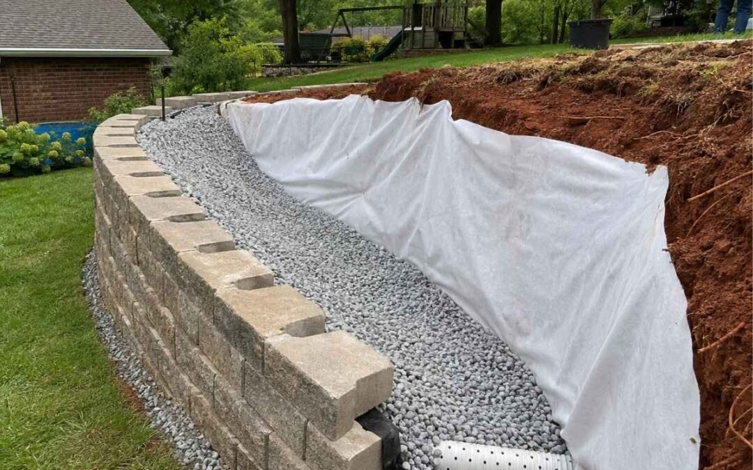
A retaining wall drainage system is the engineered network of aggregate, filter fabric, perforated pipe, and discharge outlet that intercepts water behind a wall and routes it away before it can build force against the structure. That force is hydrostatic pressure. It is the leading cause of retaining wall failure across every wall type, height, and material. In the St. Louis metropolitan area, the problem compounds because the region’s expansive smectite clay drains poorly, swells under moisture, and holds water against wall faces longer than granular soils in other markets.
This guide covers every design decision involved in building a drainage system for St. Louis clay, freeze-thaw exposure, and Metropolitan Sewer District discharge requirements. Retaining Wall & Paving Solutions designs drainage systems through its licensed in-house engineer, who integrates drainage specifications into every PE-stamped wall project.
What Is a Retaining Wall Drainage System?
A retaining wall drainage system is an integrated assembly of drainage aggregate, geotextile filter fabric, perforated collection pipe, and a discharge outlet that intercepts water behind the wall and routes it away before hydrostatic pressure can develop against the structure.
Water trapped in soil behind a retaining wall creates lateral pressure that increases with depth. At any given point, the horizontal force equals the weight of a water column from the surface down to that depth, added on top of the lateral earth pressure the wall already carries from the soil itself. A 6-foot wall retaining saturated backfill can experience roughly double the total lateral load compared to the same wall with properly drained soil. That added load pushes the wall outward at the base, initiating rotation, cracking at mortar joints, and progressive lean. That difference is not gradual. It accumulates over hours or days as water saturates clay that cannot drain on its own, and it applies the highest force at the base of the wall where structural resistance matters most. Drainage is a structural requirement, not an addition chosen for extra protection.
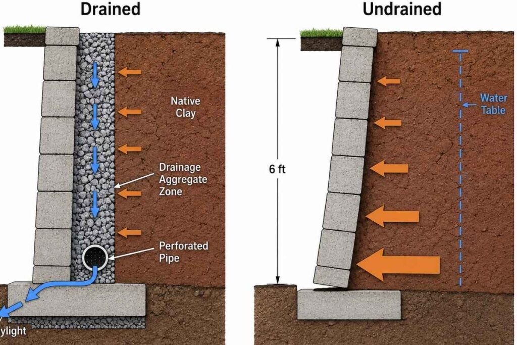
The system works because four components handle different stages of the same water path. The drainage aggregate zone, a minimum 12-inch-wide layer of clean 3/4-inch to 1-1/2-inch angular crushed stone per the NCMA SRW Installation Guide, creates void space where water migrates freely instead of pressing against the wall face. Geotextile filter fabric wraps the interface between the aggregate and the native soil, preventing fine particle migration into the stone.
Without an exit path, collected water pools at the wall base. A perforated collection pipe at the base of the aggregate zone captures water draining downward through the stone and carries it along a sloped path toward the outlet. The discharge outlet is where the pipe daylights to grade or connects to a storm drain, moving collected water away from the wall permanently. Remove any single component and the system fails: aggregate without fabric clogs, pipe without aggregate collects nothing, and an outlet without pipe has no water to route.
Why Does St. Louis Clay Soil Require Specialized Drainage Design?
St. Louis sits on smectite clay that swells when wet, shrinks when dry, and drains poorly, which means drainage systems must be oversized relative to sandy-soil regions, aggregate zones must extend the full height of the wall, and geotextile fabric selection must account for clay particle migration that can blind standard filter fabrics. The permeability coefficient of St. Louis smectite clay is orders of magnitude lower than sandy or silty soils. Water sits, not drains.
That low permeability drives a two-phase damage cycle. When the clay absorbs moisture, it expands and applies lateral force against the wall beyond the static earth pressure the structure was engineered to carry. When it dries during summer months, it shrinks and pulls away from the drainage aggregate, opening voids between the soil mass and the stone layer. Future rainfall channels through those voids directly against the wall face, bypassing the drainage zone entirely.
St. Louis averages 42 inches of annual rainfall distributed across all four seasons, with spring storms between March and May producing the highest single-event volumes. Most of that water hits soil that cannot absorb it. The freeze-thaw cycle between November and March adds a second load mechanism: water trapped in poorly drained backfill freezes, expands by roughly 9%, and applies frost heave pressure against the wall and its footing. Segmental wall units in freeze-thaw zones must meet ASTM C1372 durability requirements, but drainage prevents water from reaching the structure. A drainage system designed for St. Louis must handle two demands simultaneously: sustained saturation from clay that will not release water on its own, and episodic volume surges from spring storms and winter snowmelt.
What Are the Core Components of a Retaining Wall Drainage System?
A retaining wall drainage system consists of three material components that work together: the drainage aggregate zone that creates a water migration path, the geotextile filter fabric that prevents soil contamination of the aggregate, and the perforated collection pipe with discharge outlet that captures and routes water away from the wall. Each component is specified independently, but the system only functions when all three are sized, placed, and connected for the same site conditions.
Drainage Aggregate Specifications and Placement
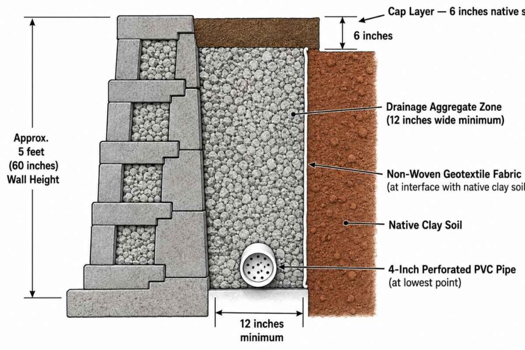
Use clean, angular crushed stone in 3/4-inch to 1-1/2-inch gradation, placed in a zone at least 12 inches wide extending from the drain pipe level to within 6 inches of the finished grade behind the wall. Angular stone is specified because the fractured faces interlock under overburden pressure and maintain void ratio where water flows. Rounded river rock does not.
The drainage aggregate zone must meet the following requirements from the NCMA SRW Installation Guide:
- Clean, free-draining coarse aggregate with no fines, dust, or organic material that would reduce void space or promote clogging
- Minimum 12-inch horizontal depth measured from the back face of the wall units to the geotextile fabric interface
- Vertical coverage from the perforated drain pipe at the base to within 6 inches of finished grade, with the top 6 inches capped using native soil or a low-permeability layer to prevent surface water from entering the aggregate directly
- Hollow cores of segmental retaining wall units filled with the same drainage aggregate, adding dead weight to the wall system while creating vertical drainage channels through the structure itself
- On sites where space behind the wall is limited, a geocomposite drain board paired with a reduced aggregate zone can substitute for the full 12-inch layer, provided the combined internal-external system meets the same flow capacity
The cap layer is the detail most often skipped. Without it, every rainstorm sends surface water straight into the aggregate zone and overwhelms the collection pipe at the base, producing the same saturated backfill condition the system was built to prevent. The aggregate zone is not a gravel pit. It is a controlled pathway designed to intercept subsurface water while deflecting surface water to grade-level drainage. Compaction of the aggregate during placement must follow lift-based procedures to avoid crushing voids closed, which permanently reduces the zone’s drainage capacity.
Geotextile Filter Fabric Selection for Clay Soils
Use non-woven geotextile fabric meeting AASHTO M 288 subsurface drainage criteria, placed between the native clay soil and the drainage aggregate zone, with the pipe wrapped separately or seated on fabric laid in the trench before aggregate placement. Woven geotextile has uniform openings that clay particles bridge and seal over time, progressively choking flow capacity until the fabric functions as a barrier rather than a filter. That failure mode is called geotextile blinding. It is the primary reason woven fabric fails in St. Louis clay. Non-woven fabric uses a random fiber matrix with variable pore sizes that resist systematic clogging because no single opening pattern exists for clay particles to exploit.
Two AASHTO M 288 properties govern fabric performance in clay: permittivity, the rate water passes through the fabric under pressure, and apparent opening size (AOS), which must be compatible with the retained soil’s particle gradation. The fabric wraps the entire interface between native soil and drainage aggregate, with a minimum 6-inch overlap at every seam to prevent clay from migrating through gaps. A separate fabric sleeve around the perforated pipe catches particles that pass the primary wrap.
Perforated Pipe Sizing, Slope, and Outlet Routing
Install a 4-inch minimum diameter perforated PVC or HDPE pipe meeting ASTM F758 at the base of the drainage aggregate zone, sloped at a minimum 2% toward a discharge outlet that daylights to an approved point away from buildings, adjacent properties, and existing drainage paths. Walls over 6 feet or walls retaining saturated clay slopes may require 6-inch pipe based on anticipated flow volume. The pipe is the only component that actively moves water out.
- Set the perforated pipe at the lowest point of the aggregate zone with perforations facing down so water rises into the pipe rather than sediment settling into the openings from above
- Slope the pipe at a minimum 2% grade (1/4 inch per foot of run) from the highest collection point toward the outlet
- Route the outlet to daylight at a point where discharged water drains onto a flat surface such as a lawn and flows away from all structures
- Connect to a storm drain where gravity daylight is not available, following MSD stormwater drainage facility requirements for tie-in approval and pipe specification
Discharged water must reach flat areas, drain away from buildings and adjacent properties, not create a nuisance on neighboring land, and not obstruct existing swales or drainage paths. St. Louis County codifies these four conditions under PM507.1 and R403.1. A pipe that dead-ends behind the wall with no outlet is the second most common drainage failure after missing geotextile. The water has nowhere to go, so it saturates the base of the wall at the exact point where hydrostatic pressure is highest.
How Does Wall Height Change Drainage System Requirements?
Wall height directly scales hydrostatic pressure, aggregate zone depth, pipe diameter requirements, and code obligations: walls under 3 feet in St. Louis County may use basic gravity drainage, walls from 3 to 4 feet require a permit and full four-component drainage system, and walls over 4 feet require PE-stamped drainage plans integrated with the structural design. The table below maps each height range to its drainage specifications, permit triggers, and engineering requirements.
| Height Range | Drainage System | Pipe Diameter | Permit Status | Engineering Requirement |
|---|---|---|---|---|
| Under 3 feet | Full four-component system recommended; minimum 12-inch aggregate zone, non-woven geotextile, 4-inch perforated pipe, gravity outlet | 4-inch standard | No building permit required in St. Louis County | No PE stamp required, but drainage design still applies in clay soil |
| 3 to 4 feet | Full four-component system required; aggregate zone extends full wall height, geotextile wraps entire soil-aggregate interface | 4-inch standard; evaluate 6-inch if retaining saturated clay | Building permit required — St. Louis County measures from top of base grade to retained grade | No PE stamp required in most jurisdictions, but permit submission must include drainage plan |
| Over 4 feet | PE-designed drainage system integrated with structural engineering; aggregate zone dimensions, geotextile grade, pipe diameter, and outlet routing specified by engineer | 6-inch recommended for saturated clay slopes; engineer specifies based on flow calculation | Building permit required; engineered drawings mandatory | PE stamp required — IBC Section 1807; RSMo §327.181 defines drainage design as part of structural engineering affecting public safety |
A wall retaining saturated clay at 2 feet generates enough hydrostatic pressure to displace a lightweight gravity wall. Permit status does not change the physics. The full four-component system applies at every height in St. Louis clay because the soil condition, not the code threshold, determines whether drainage is structurally necessary.
For walls above 4 feet, drainage is not a finishing detail added after the structural design. The engineer specifies pipe diameter, aggregate zone dimensions, geotextile type, and discharge routing as structural inputs because each one directly affects the lateral load the wall must resist. That design work qualifies as professional engineering requiring licensure under RSMo §327.181.
What Are the Most Common Retaining Wall Drainage Mistakes?
- Omitting geotextile fabric between the native clay and the drainage aggregate, allowing soil migration into the stone over 2 to 5 years
- Installing a drain pipe with no outlet or a dead-end connection, trapping water at the base of the wall
- Using rounded river rock instead of angular crushed stone, reducing void space and drainage capacity under overburden pressure
- Extending the aggregate zone only partway up the wall, leaving bare soil-to-wall contact above the drainage path
- Routing discharge toward adjacent properties, structures, or existing swales in violation of St. Louis County drainage requirements
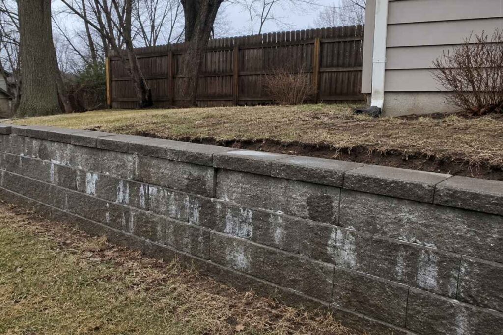
Geotextile omission is the most damaging single error. Clay particles fill aggregate voids, converting the drainage zone into a water-retaining mass pressing hydrostatic load against the wall. The process takes 2 to 5 years. Initially sound walls begin leaning without visible cause. Partial-height aggregate fails differently: water above the stone zone hits bare soil contact and concentrates stress where the wall has no drainage relief. Both produce efflorescence on the wall face as the first visible warning.
External water sources like roof downspouts, irrigation overspray, driveway runoff, and hillside surface flow cause failures that have nothing to do with how the drainage system was built. Drainage design must account for every water source reaching the wall.
How Do You Design Drainage for Tiered Retaining Walls?
Each tier in a tiered wall system requires its own independent drainage system with a separate collection pipe and outlet, because the upper tier’s drainage discharge becomes the lower tier’s water source, and failing to intercept water between tiers transfers the full hydrostatic load from the upper retained zone onto the lower wall. The upper wall’s retained soil falls within the lower wall’s structural influence zone unless the horizontal offset between tiers equals at least twice the height of the lower wall. Insufficient offset compounds the load. The lower wall carries its own lateral earth pressure plus surcharge from the upper wall’s retained soil mass.
St. Louis County caps pre-approved tiers at 8 feet combined and 6 feet per tier. Any three-tier configuration or any system exceeding those limits requires custom PE-stamped engineering that must include drainage specifications for each tier and the inter-tier zone.
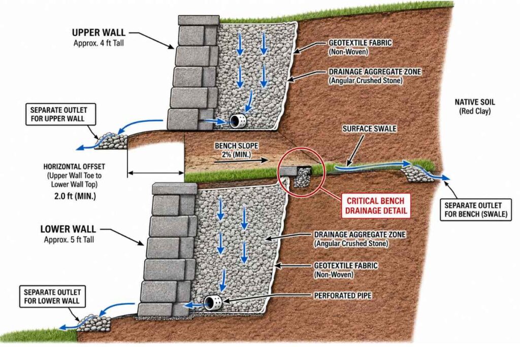
The inter-tier bench is the drainage connection most often missed. The bench must be graded to drain away from the lower wall. If the bench collects water from the upper tier’s discharge or from surface runoff, that water adds directly to the lower wall’s hydrostatic load.
Three solutions intercept bench water before it reaches the lower wall: a graded swale directing flow off the bench, a surface drain connected to a separate outlet, or a secondary perforated pipe buried at bench level. Without inter-tier drainage, a tiered system fails from the bottom up, even when each individual wall has a correctly installed internal drainage system.
What Maintenance Does a Retaining Wall Drainage System Need?
Inspect drain outlets and weep holes for flow after every major rain event, flush the perforated pipe annually in late winter before spring storms, check for efflorescence or water staining on the wall face each season, and confirm the ground behind the wall has not settled or developed sinkholes that indicate void formation in the drainage zone. St. Louis seasonal timing drives the schedule: February flush, March or April post-storm inspection, and quarterly wall face checks through the rest of the year.
- Flush the perforated pipe from the outlet end using a garden hose in late winter (February) to clear sediment accumulated during fall and winter
- Inspect all visible outlets and weep holes during or immediately after the first major spring storm — flowing or dripping water confirms the system is working; dry outlets indicate a clog or failed connection
- Check the wall face each season for new efflorescence, the white mineral deposits that signal water passing through the structure rather than through the drainage system
- Walk the ground directly behind the wall and press for soft spots or settlement, which indicate void formation where soil has migrated through failed geotextile and washed out through the pipe
- Remove woody plants within 3 feet of the wall face and trim any roots approaching the drainage zone, because root systems penetrate geotextile, displace aggregate, and crack pipe joints
Void formation is the symptom that escalates fastest. Hollow pockets inside the aggregate layer grow as fine soil continues migrating through damaged or missing fabric. Left unaddressed, the surface above can collapse suddenly. Settlement and soft spots are the only external indicators before that collapse, which is why the ground check matters more than the wall face check for detecting advanced degradation.
When Should a Licensed Engineer Design Your Drainage System?
A licensed Professional Engineer should design the drainage system whenever the wall exceeds 4 feet, retains a surcharge load from a structure or driveway, sits on a slope steeper than 3:1, involves clay soil with a high water table, or is part of a tiered system exceeding St. Louis County’s pre-approved height limits. Structural design affecting public safety qualifies as professional engineering under RSMo §327.181, the definitional section of the Missouri Engineering Practice Act (§327.011 RSMo).
- Wall height exceeds 4 feet in any Missouri jurisdiction or 3 feet in St. Louis County
- Surcharge loading from a structure, driveway, parking area, or additional slope above the wall
- Slope behind the wall steeper than 3:1, routing surface water into the retained zone
- High seasonal water table confirmed by geotechnical boring or historical site data
- Tiered system exceeding St. Louis County pre-approved limits of 8 feet combined or 6 feet per single tier
- Proximity to a foundation or utility where drainage failure would cause secondary damage
- Property owner cannot confirm groundwater conditions behind the planned wall location
The distinction is not whether drainage is needed. It always is in St. Louis clay. The distinction is whether site conditions create enough risk that drainage design requires engineering analysis rather than standard NCMA installation practice. For walls below the PE threshold, a qualified installer following the four-component system can design drainage without a PE stamp. A PE-designed system specifies pipe diameter, aggregate zone dimensions, geotextile grade, outlet routing, and anticipated flow capacity based on site-specific soil permeability and rainfall intensity data.